681
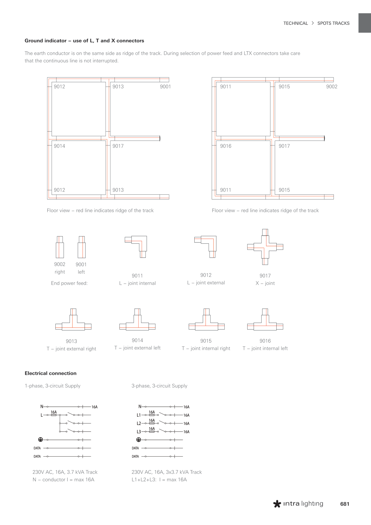
Ground indicator − use of L, T and X connectors
The earth conductor is on the same side as ridge of the track. During selection of power feed and LTX connectors take care
that the continuous line is not interrupted.
Floor view − red line indicates ridge of the track
9012
9014
9012
9013
9001
9017
9013
Floor view − red line indicates ridge of the track
9011
9016
9011
9015
9002
9017
9015
End power feed:
9002
right
9001
left
9013
T − joint external right
9011
L − joint internal
9012
L − joint external
9014
T − joint external left
9015
T − joint internal right
9016
T − joint internal left
9017
X − joint
Electrical connection
1-phase, 3-circuit Supply
230V AC, 16A, 3.7 kVA Track
N − conductor I = max 16A
3-phase, 3-circuit Supply
230V AC, 16A, 3x3.7 kVA Track
L1+L2+L3: I = max 16A
16A
16A
16A
16A
16A
16A
16A
L3
L2
N
L1
DATA
DATA
16A
16A
DATA
DATA
L
N
16A
16A
16A
16A
16A
16A
16A
L3
L2
N
L1
DATA
DATA
16A
16A
DATA
DATA
L
N
TECHNICAL SPOTS TRACKS


