458
KNX Heating, ventilation, air conditioning
Specifications
Order No.
P. unit
PS
Specifications
Order No.
P. unit
PS
Gira electrical installation systems
Price system (PS) ≠ 1, 14: reduced discount
KNX system
devices, actuators,
sensors
DRA plus
2162002162 00
1
26
C Optional accessories
therm.servo 230 V 2169 00
D
266
Features
- The room actuator controls three functions simultaneously in one
device, such as lighting, blind and heating. The four relay outputs
can be set either for blind operation or alternatively for switching
operation in the ETS (Engineering Tool Software). Mixed
operation is also possible.
- Two switching outputs make one blind output.
- In addition, there are two further electronic switching outputs for
the control of servos.
Switching operation
- The room actuator with its relay contacts controls electrical
devices such as lighting systems. The relay contacts have
flip-flop contacts, so that the last set switching condition remains
unchanged even if the power supply fails.
- Functional properties for each output: a wide spectrum of time
functions, logical links, scenes, block functions or restraints,
extended feedback, cyclical monitoring of incoming switching
telegrams and an elapsed operating time meter.
Blind operation
- The room actuator uses its relay contacts to control electrically
operated blinds, shutters, awnings, ventilation flaps,or similar
hangings with a mains voltage of AC 230 V.
- Functional properties for each output channel: separately
parameterisable movement times, extended feedback functions,
assignments of up to 5 various safety functions, a comprehensive
solar protection function and the integrating in scenes or
restraints.
Room temperature control
- Two further electronic switching outputs are used for silent
operation of electro thermic servos for heating or cooling
systems.
- Continuous correcting variable telegrams are implemented in a
pulse width modulated output signal (PWM). With this the servos
can be continuously controlled. Alternatively, implementing
switching correcting variables is also possible. Status message
for the valve position and cyclical monitoring of correcting
variable telegrams.
- Emergency mode in case of bus voltage failure or bus/mains
voltage recovery plus forced setting via bus telegram for summer
and winter mode.
- An alarm is triggered in case of short circuit or overload of the
switching output and position protection for the valves. De-
energised closed or open valve drives can be connected
- Monitoring of mains voltage supply, and in cases of malfunction,
the transmission of an alarm message on the bus.
- Group messages "all valves closed" and "largest correcting
variable".
Technical data
KNX medium:
TP256
Heating outputs
- Switching contact:
Triac
- Number:
2
- Number of drives per output:
max. 4
- Switching current:
5 to 50 mA
- Maximum switch-on current:
1.5 A, 2 s
Switching contact:
µ contact, 4 x zero-voltage NO
contact each
Switching capacity AC 230 V:
16 A / AC1 or 6 A / AC3
Maximum switch-on current
- 200 µs:
800 A
- 20 ms:
165 A
Connected load
- Ohmic load:
3000 W
- Capacitive load AC 230 V:
16 A, max. 140 µF
- Light bulbs:
3000 W
- HV halogen lamps:
2500 W
- Wound transformer:
1200 VA
- Tronic transformer:
1500 W
- Fluorescent lamps, parallel-
compensated:
1160 VA
- Mercury-vapour lamps,
uncompensated:
1000 W
- Mercury-vapour lamps,
parallel-compensated:
1160 W
- Motors (blind or fan):
1380 VA
Connections
- KNX:
Connection and junction terminal
- Load:
load via screw terminals
- Connections:
max. 4 mm²
Dimensions
- Modular widths (MW):
4
Notes
- VDE approval in accordance with EN 60669-1, EN 60669-2-1.
- Installation on DIN top-hat rail.
Scope of supply
- KNX connection and junction terminal included in the scope of
supply.
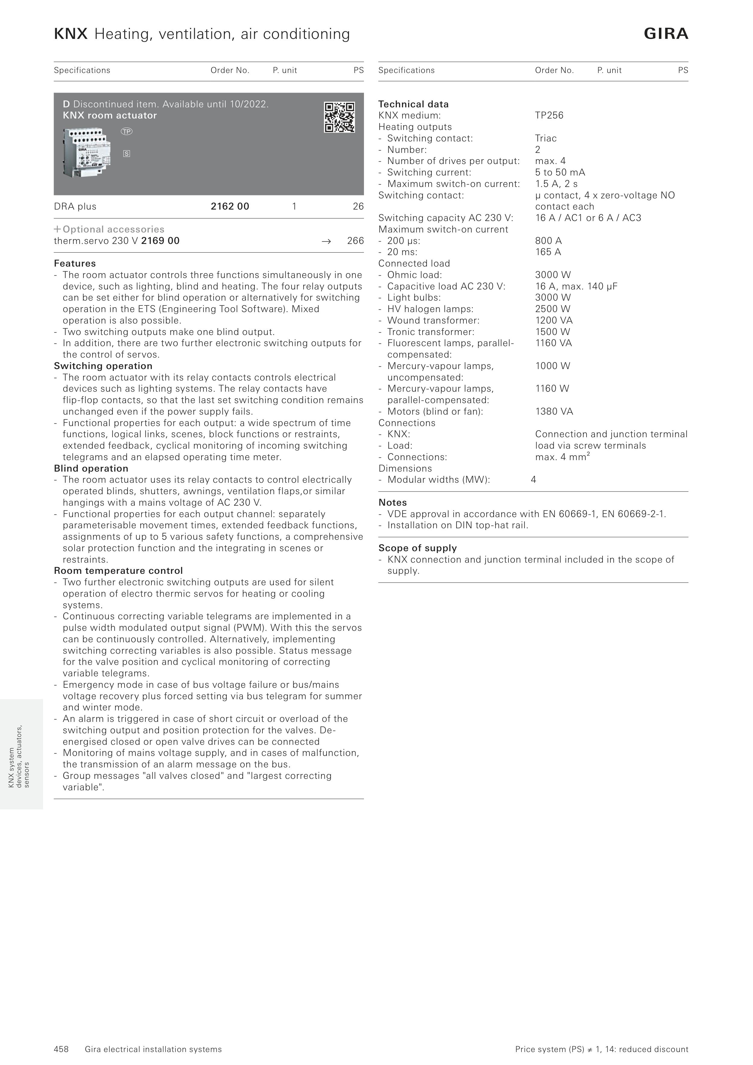
D Discontinued item. Available until 10/2022.
KNX room actuator


