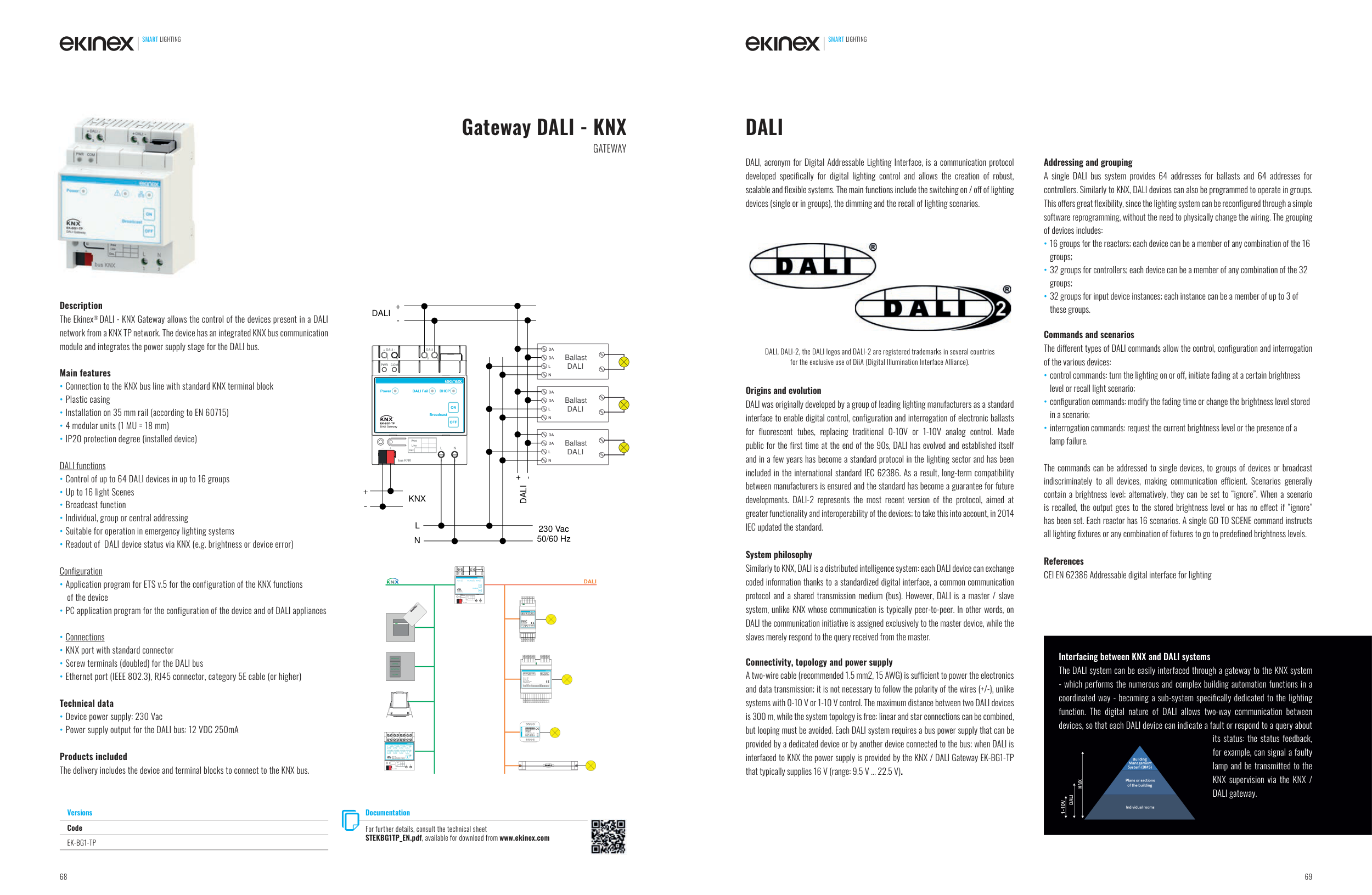
Description
The Ekinex® DALI - KNX Gateway allows the control of the devices present in a DALI
network from a KNX TP network. The device has an integrated KNX bus communication
module and integrates the power supply stage for the DALI bus.
Main features
• Connection to the KNX bus line with standard KNX terminal block
• Plastic casing
• Installation on 35 mm rail (according to EN 60715)
• 4 modular units (1 MU = 18 mm)
• IP20 protection degree (installed device)
DALI functions
• Control of up to 64 DALI devices in up to 16 groups
• Up to 16 light Scenes
• Broadcast function
• Individual, group or central addressing
• Suitable for operation in emergency lighting systems
• Readout of DALI device status via KNX (e.g. brightness or device error)
Configuration
• Application program for ETS v.5 for the configuration of the KNX functions
of the device
• PC application program for the configuration of the device and of DALI appliances
• Connections
• KNX port with standard connector
• Screw terminals (doubled) for the DALI bus
• Ethernet port (IEEE 802.3), RJ45 connector, category 5E cable (or higher)
Technical data
• Device power supply: 230 Vac
• Power supply output for the DALI bus: 12 VDC 250mA
Products included
The delivery includes the device and terminal blocks to connect to the KNX bus.
Gateway DALI - KNX
GATEWAY
+
-
KNX
L
N
230 Vac
50/60 Hz
3
4
5
6
1
2
L
N
bus KNX
Dev.
Line
Area
PWR
COM
+ DALI -
+ DALI -
DALI
+
-
DA
Ballast
DALI
DA
L
N
DA
Ballast
DALI
DA
L
N
DA
Ballast
DALI
DA
L
N
DALI +
-
DALI, acronym for Digital Addressable Lighting Interface, is a communication protocol
developed specifically for digital lighting control and allows the creation of robust,
scalable and flexible systems. The main functions include the switching on / off of lighting
devices (single or in groups), the dimming and the recall of lighting scenarios.
Origins and evolution
DALI was originally developed by a group of leading lighting manufacturers as a standard
interface to enable digital control, configuration and interrogation of electronic ballasts
for fluorescent tubes, replacing traditional 0-10V or 1-10V analog control. Made
public for the first time at the end of the 90s, DALI has evolved and established itself
and in a few years has become a standard protocol in the lighting sector and has been
included in the international standard IEC 62386. As a result, long-term compatibility
between manufacturers is ensured and the standard has become a guarantee for future
developments. DALI-2 represents the most recent version of the protocol, aimed at
greater functionality and interoperability of the devices; to take this into account, in 2014
IEC updated the standard.
System philosophy
Similarly to KNX, DALI is a distributed intelligence system: each DALI device can exchange
coded information thanks to a standardized digital interface, a common communication
protocol and a shared transmission medium (bus). However, DALI is a master / slave
system, unlike KNX whose communication is typically peer-to-peer. In other words, on
DALI the communication initiative is assigned exclusively to the master device, while the
slaves merely respond to the query received from the master.
Connectivity, topology and power supply
A two-wire cable (recommended 1.5 mm2, 15 AWG) is sufficient to power the electronics
and data transmission; it is not necessary to follow the polarity of the wires (+/-), unlike
systems with 0-10 V or 1-10 V control. The maximum distance between two DALI devices
is 300 m, while the system topology is free: linear and star connections can be combined,
but looping must be avoided. Each DALI system requires a bus power supply that can be
provided by a dedicated device or by another device connected to the bus; when DALI is
interfaced to KNX the power supply is provided by the KNX / DALI Gateway EK-BG1-TP
that typically supplies 16 V (range: 9.5 V ... 22.5 V).
Addressing and grouping
A single DALI bus system provides 64 addresses for ballasts and 64 addresses for
controllers. Similarly to KNX, DALI devices can also be programmed to operate in groups.
This offers great flexibility, since the lighting system can be reconfigured through a simple
software reprogramming, without the need to physically change the wiring. The grouping
of devices includes:
• 16 groups for the reactors; each device can be a member of any combination of the 16
groups;
• 32 groups for controllers; each device can be a member of any combination of the 32
groups;
• 32 groups for input device instances; each instance can be a member of up to 3 of
these groups.
Commands and scenarios
The different types of DALI commands allow the control, configuration and interrogation
of the various devices:
• control commands: turn the lighting on or off , initiate fading at a certain brightness
level or recall light scenario;
• configuration commands: modify the fading time or change the brightness level stored
in a scenario;
• interrogation commands: request the current brightness level or the presence of a
lamp failure.
The commands can be addressed to single devices, to groups of devices or broadcast
indiscriminately to all devices, making communication efficient. Scenarios generally
contain a brightness level; alternatively, they can be set to “ignore”. When a scenario
is recalled, the output goes to the stored brightness level or has no effect if “ignore”
has been set. Each reactor has 16 scenarios. A single GO TO SCENE command instructs
all lighting fixtures or any combination of fixtures to go to predefined brightness levels.
References
CEI EN 62386 Addressable digital interface for lighting
DALI
DALI, DALI-2, the DALI logos and DALI-2 are registered trademarks in several countries
for the exclusive use of DiiA (Digital Illumination Interface Alliance).
Versions
Code
EK-BG1-TP
Documentation
For further details, consult the technical sheet
STEKBG1TP_EN.pdf, available for download from www.ekinex.com
Interfacing between KNX and DALI systems
The DALI system can be easily interfaced through a gateway to the KNX system
- which performs the numerous and complex building automation functions in a
coordinated way - becoming a sub-system specifi cally dedicated to the lighting
function. The digital nature of DALI allows two-way communication between
devices, so that each DALI device can indicate a fault or respond to a query about
its status: the status feedback,
for example, can signal a faulty
lamp and be transmitted to the
KNX supervision via the KNX /
DALI gateway.
1-10V
DALI
KNX
Plans or sections
of the building
Building
Management
System (BMS)
Individual rooms
SMART LIGHTING
SMART LIGHTING
68
69


