173
DESIGN - STEFANO DALL’OSSO
135
71
Cod.
L1
7061
880
7062
1180
7063
1480
7064
2258
7065
2858
Cod.
L2
7051
778
7052
1078
7053
1378
7054
2156
7055
2756
L1
L1
L2
L2
352
L2
L2
1180
L2
1078
L2
1078
L2
1078
L2
= 5492
1078
5492 + 6 mm
= 5498
71
73
L1
1180
L2
1078
L2
1078
= 3336
3336 + 4 mm
= 3340
71
73
353
353
LUCE AL METRO
MODULAR SYSTEM
ACCESSORIES
352
End cap
Coated steel cap for end line module
(each assembled system required one single cap)
353
Module coupling device
356
Bracket for plasterboard mounting
(2 x cod. 7061 - 7051; 3 x cod. 7062 - 7052 - 7063 - 7053;
6 x cod. 7064 - 7054 - 7065 - 7055)
Size (mm)
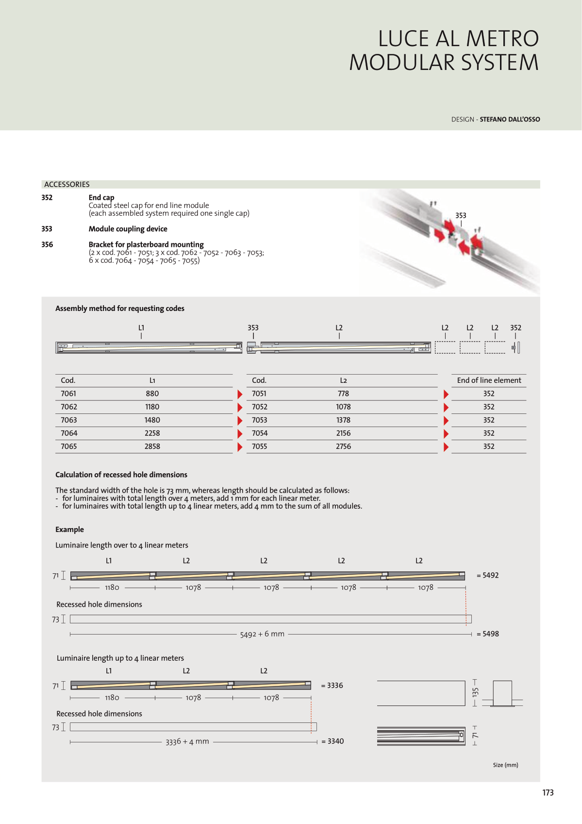
Assembly method for requesting codes
Calculation of recessed hole dimensions
The standard width of the hole is 73 mm, whereas length should be calculated as follows:
- for luminaires with total length over 4 meters, add 1 mm for each linear meter.
- for luminaires with total length up to 4 linear meters, add 4 mm to the sum of all modules.
Example
Luminaire length over to 4 linear meters
End of line element
352
352
352
352
352
Recessed hole dimensions
Recessed hole dimensions
Luminaire length up to 4 linear meters


