46
47
The use of a support every 100
cm of the track allows for a maxi-
mum load of 10 Kg per meter.
Install the ceiling/wall mounting
devices, in correspondence with
the end parts of the installation
and near the joints.
L’utilizzo di un sostegno ogni
100 cm di binario consente un
carico massimo di 10 Kg al m.
Utilizzare i dispositivi di fissag-
gio a softto/parete mettendoli
in corrispondenza delle parti
terminali dell’installazione ed in
prossimità delle giunzioni.
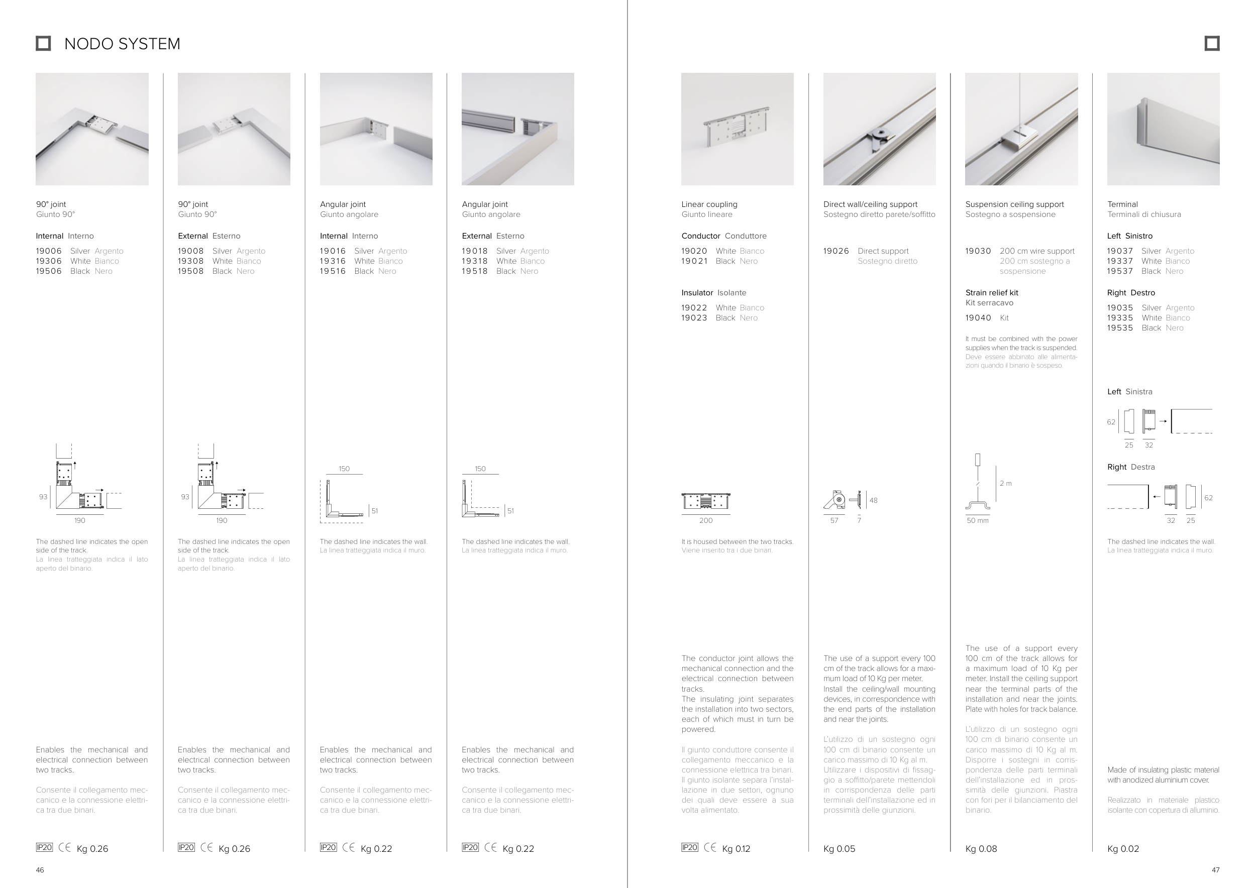
Direct wall/ceiling support
Sostegno diretto parete/softto
19026
Direct support
Sostegno diretto
The use of a support every
100 cm of the track allows for
a maximum load of 10 Kg per
meter. Install the ceiling support
near the terminal parts of the
installation and near the joints.
Plate with holes for track balance.
L’utilizzo di un sostegno ogni
100 cm di binario consente un
carico massimo di 10 Kg al m.
Disporre i sostegni in corris-
pondenza delle parti terminali
dell’installazione ed in pros-
simità delle giunzioni. Piastra
con fori per il bilanciamento del
binario.
Suspension ceiling support
Sostegno a sospensione
19030
200 cm wire support
200 cm sostegno a
sospensione
Kg 0.05
Kg 0.08
7
57
48
Strain relief kit
Kit serracavo
19040
Kit
It must be combined with the power
supplies when the track is suspended.
Deve essere abbinato alle alimenta-
zioni quando il binario è sospeso.
90° joint
Giunto 90°
Enables the mechanical and
electrical connection between
two tracks.
Consente il collegamento mec-
canico e la connessione elettri-
ca tra due binari.
90° joint
Giunto 90°
Angular joint
Giunto angolare
Enables the mechanical and
electrical connection between
two tracks.
Consente il collegamento mec-
canico e la connessione elettri-
ca tra due binari.
Angular joint
Giunto angolare
Enables the mechanical and
electrical connection between
two tracks.
Consente il collegamento mec-
canico e la connessione elettri-
ca tra due binari.
19006
19306
19506
Silver
White
Black
19008
19308
19508
1 9 0 1 6
1 9 3 1 6
1 9 5 1 6
Silver
White
Black
Silver
White
Black
Kg 0.26
Kg 0.26
Kg 0.22
The dashed line indicates the wall.
La linea tratteggiata indica il muro.
The dashed line indicates the open
side of the track.
La linea tratteggiata indica il lato
aperto del binario.
The dashed line indicates the open
side of the track.
La linea tratteggiata indica il lato
aperto del binario.
The dashed line indicates the wall.
La linea tratteggiata indica il muro.
1 9 0 1 8
1 9 3 1 8
1 9 5 1 8
Silver
White
Black
Kg 0.22
Enables the mechanical and
electrical connection between
two tracks.
Consente il collegamento mec-
canico e la connessione elettri-
ca tra due binari.
Internal Interno
External Esterno
External Esterno
Internal Interno
Argento
Bianco
Nero
Argento
Bianco
Nero
Argento
Bianco
Nero
Argento
Bianco
Nero
190
93
190
93
51
150
51
150
The conductor joint allows the
mechanical connection and the
electrical connection between
tracks.
The insulating joint separates
the installation into two sectors,
each of which must in turn be
powered.
Il giunto conduttore consente il
collegamento meccanico e la
connessione elettrica tra binari.
Il giunto isolante separa l’instal-
lazione in due settori, ognuno
dei quali deve essere a sua
volta alimentato.
Linear coupling
Giunto lineare
19020
1 9 0 2 1
19022
19023
Kg 0.12
It is housed between the two tracks.
Viene inserito tra i due binari.
Conductor Conduttore
White
Black
White
Black
Insulator Isolante
Bianco
Nero
Bianco
Nero
200
Left Sinistra
Right Destra
19035
19335
19535
Silver
White
Black
Argento
Bianco
Nero
Right Destro
Terminal
Terminali di chiusura
Made of insulating plastic material
with anodized aluminium cover.
Realizzato in materiale plastico
isolante con copertura di alluminio.
Kg 0.02
Left Sinistro
19037
19337
19537
Silver
White
Black
Argento
Bianco
Nero
NODO SYSTEM
50 mm
2 m
62
25
32
62
25
32
The dashed line indicates the wall.
La linea tratteggiata indica il muro.