Additional planning notes for Vario cooling 400 series
The side walls of the adjacent cabinetry have to be dimensionally stable, as the Vario
cooling appliances are secured in the niche with only an anti-tilt bracket on the top
back and on the bottom at the side.
Vario cooling appliances can be installed handle to handle as a side-by-side com-
bination. In this case the side-by-side installation kit RA 460 000 is required. If the
distance between the appliances is greater than 16 mm or less than 160 mm or the
environment very humid the additional side heating element RA 460 013 needs to be
installed between the appliances to avoid condensation.
If the appliances are combined hinge to handle in a very humid environment the
additional side heating element RA 460 013 is required as well. It can be omitted
if the distance between the appliances is greater than 160 mm. The additional side
heating element RA 460 013 does not take up any additional space. It is already
included in the niche dimensions.
If the Vario cooling appliances are joined together hinge to hinge an additional
stable side wall must be foreseen.
If restrictions in use are accepted (no simultaneous opening of the doors possible)
the appliances can be joined together directly, using the side-by-side installation
accessory RA 460 000.
When installing a Vario cooling appliance from the 400 series handleless next to a
BO/BM/BS/CM from the oven 400 series, a minimum lateral distance of 30 mm is
required, if the door of the Vario cooling appliance opens towards the BO/BM/BS/CM.
When installing a Vario cooling appliance from the 400 series next to a BO/BM/BS
from the ovens 400 series, a lateral distance of 60 mm is required, if the BO/BM/BS
retrofitted handle is on the same side as the Vario cooling appliance door hinge.
For the same installation next to a BOP/BMP/BSP from the ovens 200 series,
a distance of 40 mm is required.
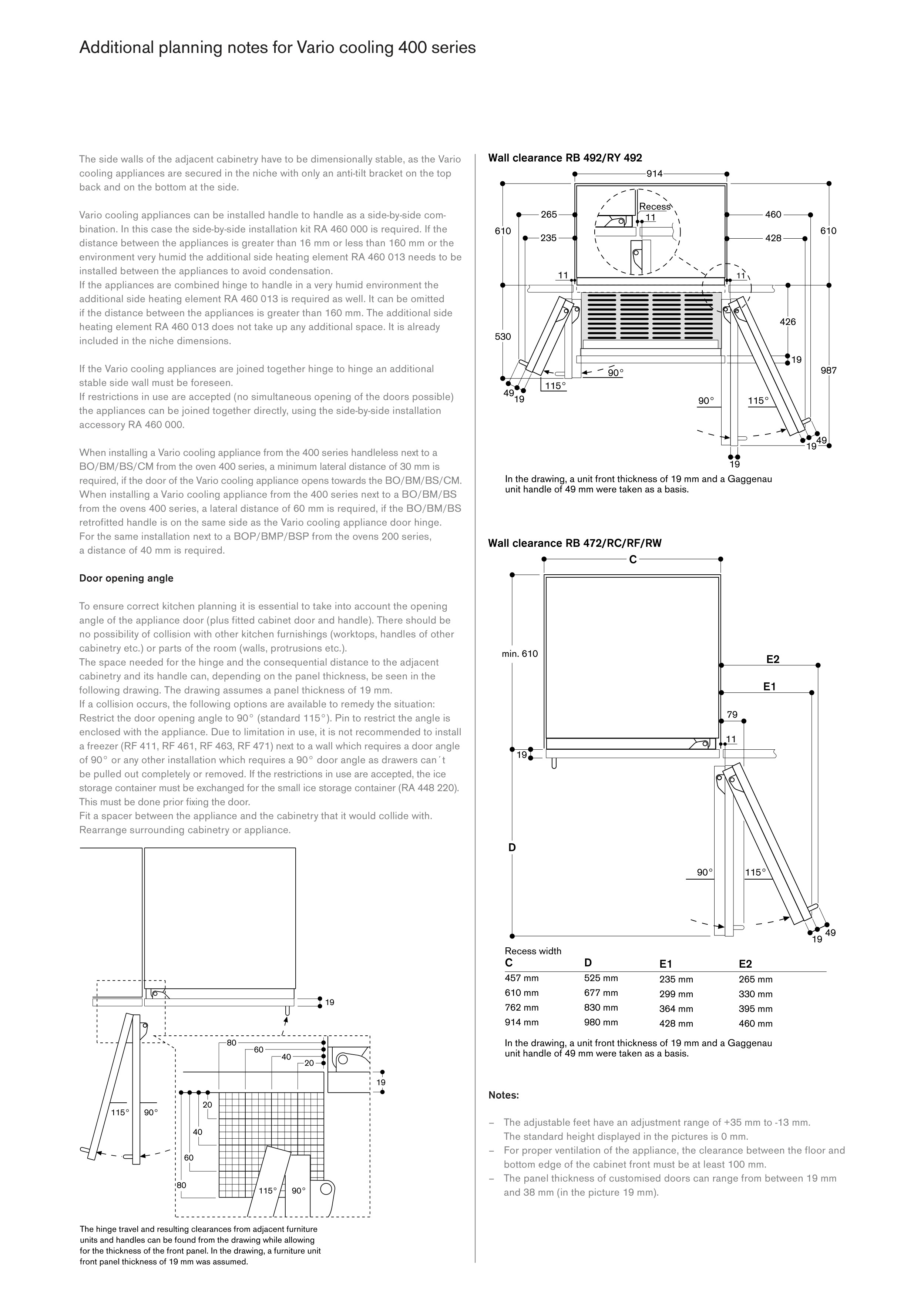
Door opening angle
To ensure correct kitchen planning it is essential to take into account the opening
angle of the appliance door (plus fitted cabinet door and handle). There should be
no possibility of collision with other kitchen furnishings (worktops, handles of other
cabinetry etc.) or parts of the room (walls, protrusions etc.).
The space needed for the hinge and the consequential distance to the adjacent
cabinetry and its handle can, depending on the panel thickness, be seen in the
following drawing. The drawing assumes a panel thickness of 19 mm.
If a collision occurs, the following options are available to remedy the situation:
Restrict the door opening angle to 90° (standard 115°). Pin to restrict the angle is
enclosed with the appliance. Due to limitation in use, it is not recommended to install
a freezer (RF 411, RF 461, RF 463, RF 471) next to a wall which requires a door angle
of 90° or any other installation which requires a 90° door angle as drawers can´t
be pulled out completely or removed. If the restrictions in use are accepted, the ice
storage container must be exchanged for the small ice storage container (RA 448 220).
This must be done prior fixing the door.
Fit a spacer between the appliance and the cabinetry that it would collide with.
Rearrange surrounding cabinetry or appliance.
Notes:
– The adjustable feet have an adjustment range of +35 mm to -13 mm.
The standard height displayed in the pictures is 0 mm.
– For proper ventilation of the appliance, the clear ance between the floor and
bottom edge of the cabinet front must be at least 100 mm.
– The panel thickness of customised doors can range from between 19 mm
and 38 mm (in the picture 19 mm).


