RESOURCES
TECHNICAL INFORMATION
CALCULATING VOLTAGE DROP:
Step 1:
Amps (Watts/Voltage) x Run/Length x 2 (for AC circuit) x Resistance per Foot(1) = Voltage
Drop (in Volts)
Step 2:
- For 12v systems add voltage drop to 12 to determine tap to use.
- For 24v systems add voltage drop to 24 to determine tap to use.
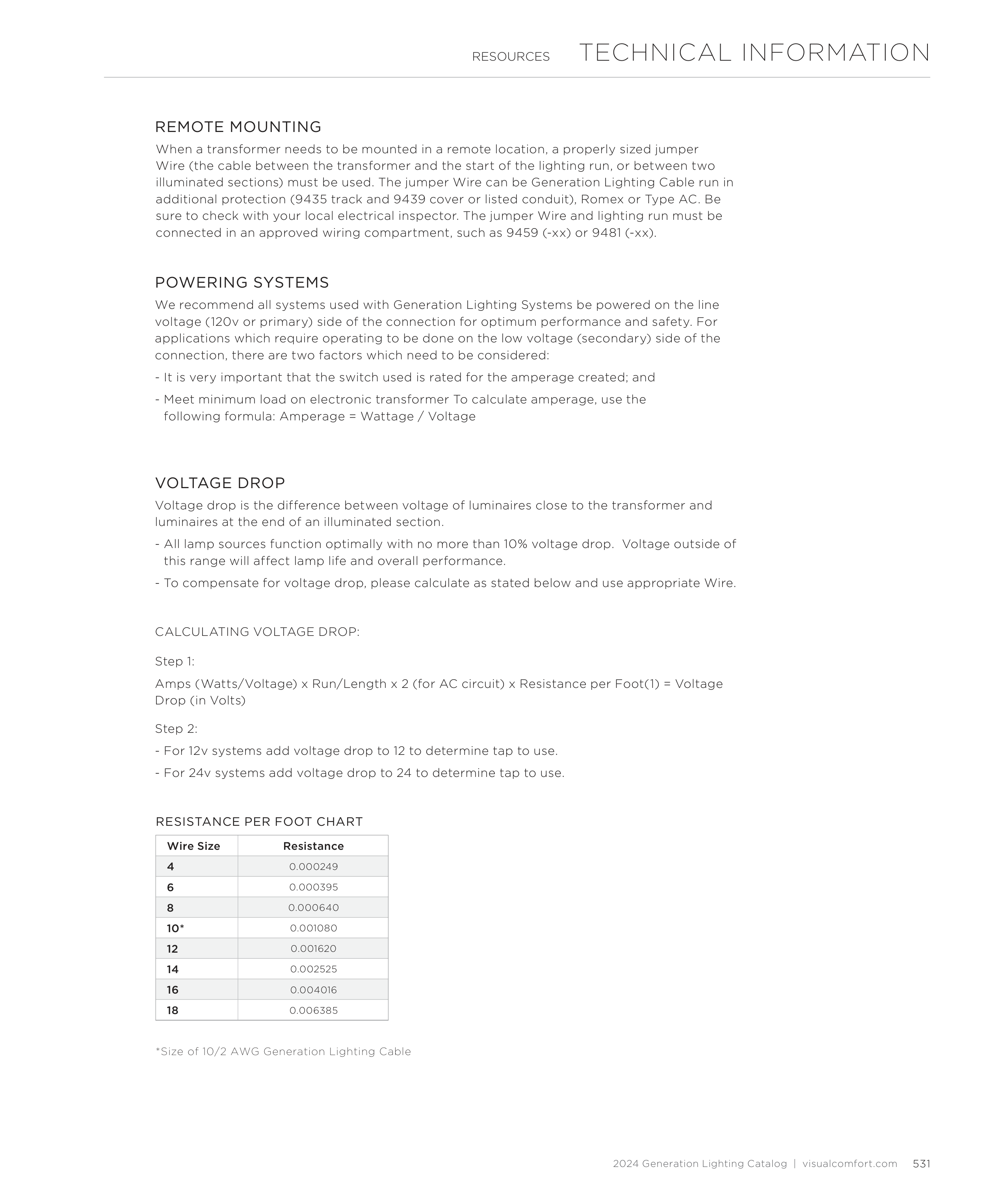
Wire Size
Resistance
4
0.000249
6
0.000395
8
0.000640
10*
0.001080
12
0.001620
14
0.002525
16
0.004016
18
0.006385
RESISTANCE PER FOOT CHART
*Size of 10/2 AWG Generation Lighting Cable
When a transformer needs to be mounted in a remote location, a properly sized jumper
Wire (the cable between the transformer and the start of the lighting run, or between two
illuminated sections) must be used. The jumper Wire can be Generation Lighting Cable run in
additional protection (9435 track and 9439 cover or listed conduit), Romex or Type AC. Be
sure to check with your local electrical inspector. The jumper Wire and lighting run must be
connected in an approved wiring compartment, such as 9459 (-xx) or 9481 (-xx).
REMOTE MOUNTING
We recommend all systems used with Generation Lighting Systems be powered on the line
voltage (120v or primary) side of the connection for optimum performance and safety. For
applications which require operating to be done on the low voltage (secondary) side of the
connection, there are two factors which need to be considered:
- It is very important that the switch used is rated for the amperage created; and
- Meet minimum load on electronic transformer To calculate amperage, use the
following formula: Amperage = Wattage / Voltage
POWERING SYSTEMS
Voltage drop is the difference between voltage of luminaires close to the transformer and
luminaires at the end of an illuminated section.
- All lamp sources function optimally with no more than 10% voltage drop. Voltage outside of
this range will affect lamp life and overall performance.
- To compensate for voltage drop, please calculate as stated below and use appropriate Wire.
VOLTAGE DROP
531
2024 Generation Lighting Catalog | visualcomfort.com