#theilluminationcollective
www.reggiani.net
T16
Technical info
Wiring guidelines
• The cables should be run separately from the mains connections and mains ca-
bles to ensure good EMC conditions.
• The LED wiring should be kept as short as possible to ensure good EMC. The
max. secondary cable length is 2m (4 m circuit).
• Secondary switching is not permitted.
• The LED Driver has no inverse-polarity protection on the secondary side.
Wrong polarity can damage LED modules with no inverse-polarity protection.
• Wrong wiring of the LED Drivers can lead to malfunction or irreparable damge.
Hot plug-in
Hot plug-in is not supported due to residual output voltage of <0 V. If a LED load
is connected, the device has to be restarted before the output will be activated
again.
Earth connection
The earth connection is conducted as protection earth (PE). If the LED Driver will
be earthed, protection earth (PE) has to be used. There is no earth connection re-
quired for the functionality of the LED Driver. Earth connection is recommended
to improve following behavior:
• Electromagnetic interferences (EMI)
• Transmission of mains transients to the LED output.
If the single-phase power supply voltage is drawn from a three-phase system:
ECGs in 3-phase operation
Overvoltage/undervoltage/no neutral conductor
1. Check whether the line voltage is within the application range of the ECF (AC/
DC range from 198 V to 254 V for example).
2. The mains connection should only be made to the luminaire terminal. For lumi-
naires or luminaire groups in 3-phase circuits.
3. Make absolutely sure that the neutral conductor is correctly connected or dis-
connected when no voltage is present.
4. Cables should only be connected or disconnected when no voltage is present.
5. For 3 x 230/240 V supply networks in triangular circuit arrangements, protec-
tion by way of common disconnection of the phase conductor is necessary.
12
3
N
L 1
L 2
L 3
Luminaire
with ECG
The diagram above shows the wiring for luminaires or luminaire groups in 3-phase
circuits and with a common neutral conductor. If the common neutral conductor
is interrupted in a 3-phase star configuration and voltage is present, then lumi-
naires or groups of luminaries may be exposed to unacceptably high voltages and
the electric control gears may be destroyed.
Note
- In new systems, the loads must not be connected when the insulation resist-
ance is measured with 500 V DC, as according to VDE 0100-600 Section 9.
The neutral conductor (N) and protective earth (PE) must not be electrically
connected in any way while this is being done. For this insulation measure-
ment (500V= to
), the neutral conductor disconnection terminal may only be
EN Guidelines for selecting and installing LED drivers
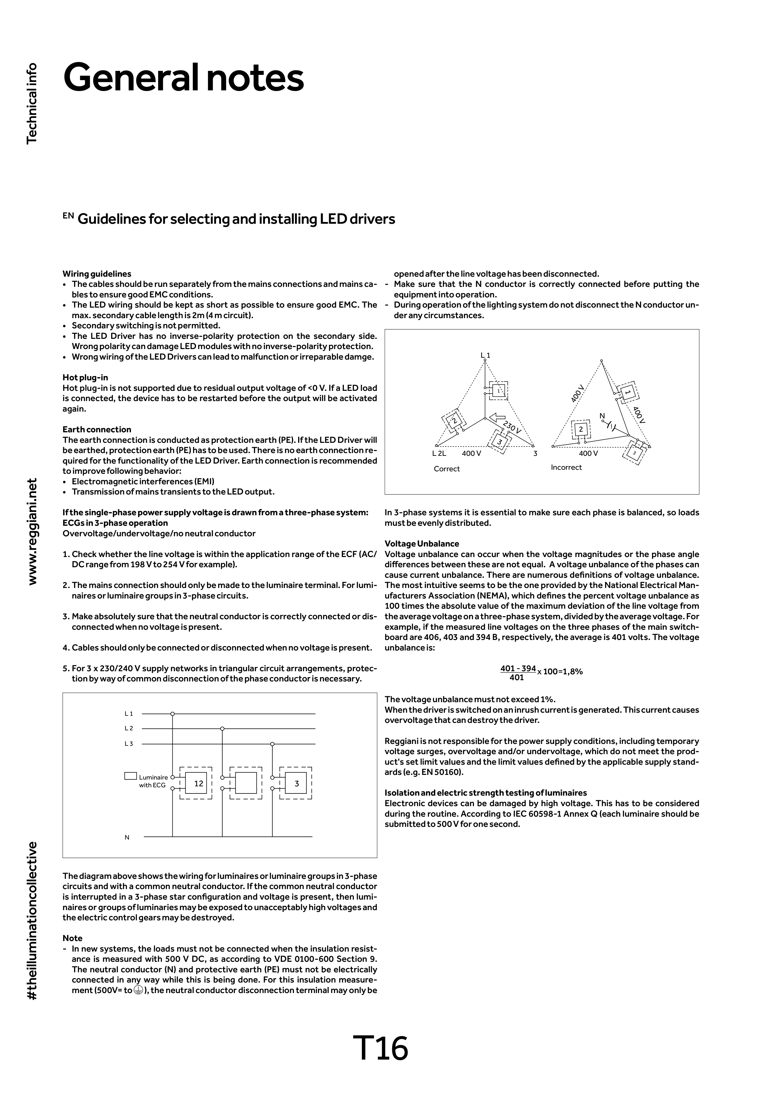
opened after the line voltage has been disconnected.
- Make sure that the N conductor is correctly connected before putting the
equipment into operation.
- During operation of the lighting system do not disconnect the N conductor un-
der any circumstances.
1
3
1
L 2L
3
400 V
230 V
400 V
400 V
N
400 V
L 1
Correct
Incorrect
2
3
2
In 3-phase systems it is essential to make sure each phase is balanced, so loads
must be evenly distributed.
Voltage Unbalance
Voltage unbalance can occur when the voltage magnitudes or the phase angle
differences between these are not equal. A voltage unbalance of the phases can
cause current unbalance. There are numerous definitions of voltage unbalance.
The most intuitive seems to be the one provided by the National Electrical Man-
ufacturers Association (NEMA), which defines the percent voltage unbalance as
100 times the absolute value of the maximum deviation of the line voltage from
the average voltage on a three-phase system, divided by the average voltage. For
example, if the measured line voltages on the three phases of the main switch-
board are 406, 403 and 394 B, respectively, the average is 401 volts. The voltage
unbalance is:
401 - 394 x 100=1,8%
401
The voltage unbalance must not exceed 1%.
When the driver is switched on an inrush current is generated. This current causes
overvoltage that can destroy the driver.
Reggiani is not responsible for the power supply conditions, including temporary
voltage surges, overvoltage and/or undervoltage, which do not meet the prod-
uct's set limit values and the limit values defined by the applicable supply stand-
ards (e.g. EN 50160).
Isolation and electric strength testing of luminaires
Electronic devices can be damaged by high voltage. This has to be considered
during the routine. According to IEC 60598-1 Annex Q (each luminaire should be
submitted to 500 V for one second.
General notes