#theilluminationcollective
www.reggiani.net
T17
Technical info
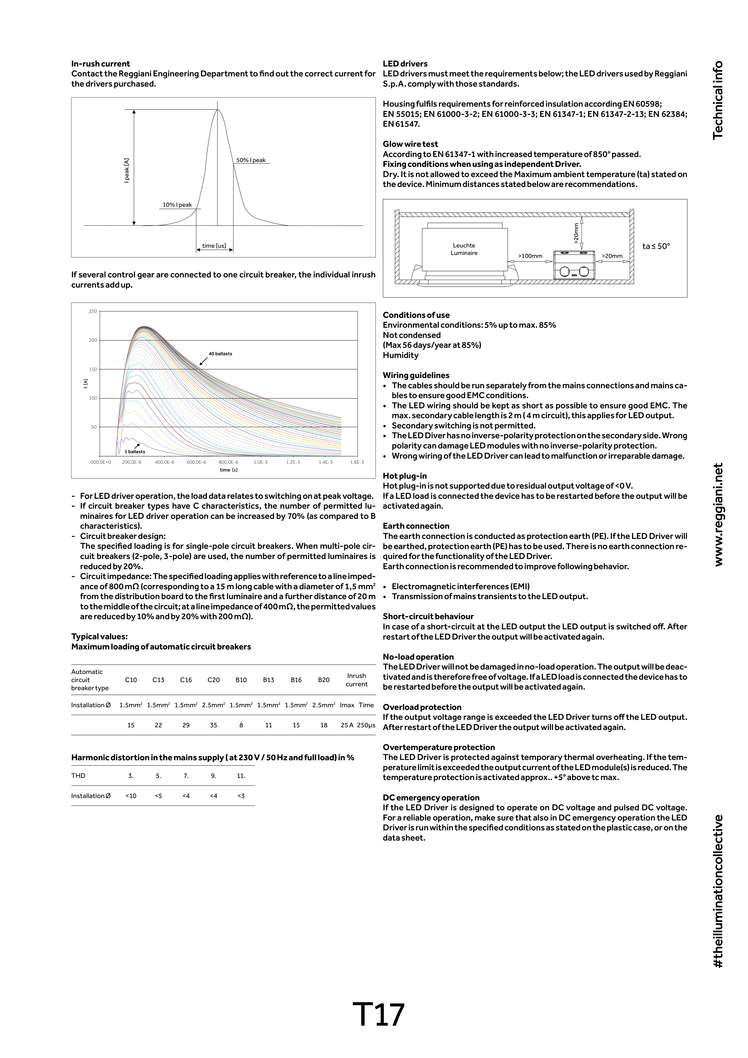
In-rush current
Contact the Reggiani Engineering Department to find out the correct current for
the drivers purchased.
10% I peak
I peak [A]
time [us]
50% I peak
If several control gear are connected to one circuit breaker, the individual inrush
currents add up.
250
200
150
100
50
000,0E+0
200,0E-6
400,0E-6
600,0E-6
800,0E-6
1,0E-3
1,2E-3
1,4E-3
1,6E-3
time [s]
I [A]
40 ballasts
1 ballasts
- For LED driver operation, the load data relates to switching on at peak voltage.
- If circuit breaker types have C characteristics, the number of permitted lu-
minaires for LED driver operation can be increased by 70% (as compared to B
characteristics).
- Circuit breaker design:
The specified loading is for single-pole circuit breakers. When multi-pole cir-
cuit breakers (2-pole, 3-pole) are used, the number of permitted luminaires is
reduced by 20%.
- Circuit impedance: The specified loading applies with reference to a line imped-
ance of 800 mΩ (corresponding to a 15 m long cable with a diameter of 1,5 mm2
from the distribution board to the first luminaire and a further distance of 20 m
to the middle of the circuit; at a line impedance of 400 mΩ, the permitted values
are reduced by 10% and by 20% with 200 mΩ).
Typical values:
Maximum loading of automatic circuit breakers
Automatic
circuit
breaker type
C10
C13
C16
C20
B10
B13
B16
B20
Inrush
current
Installation Ø
1.5mm2 1.5mm2 1.5mm2 2.5mm2 1.5mm2 1.5mm2 1.5mm2 2.5mm2 Imax Time
15
22
29
35
8
11
15
18
25 A 250μs
Harmonic distortion in the mains supply ( at 230 V / 50 Hz and full load) in %
THD
3.
5.
7.
9.
11.
Installation Ø
<10
<5
<4
<4
<3
LED drivers
LED drivers must meet the requirements below; the LED drivers used by Reggiani
S.p.A. comply with those standards.
Housing fulfils requirements for reinforced insulation according EN 60598;
EN 55015; EN 61000-3-2; EN 61000-3-3; EN 61347-1; EN 61347-2-13; EN 62384;
EN 61547.
Glow wire test
According to EN 61347-1 with increased temperature of 850° passed.
Fixing conditions when using as independent Driver.
Dry. It is not allowed to exceed the Maximum ambient temperature (ta) stated on
the device. Minimum distances stated below are recommendations.
ta ≤ 50°
Leuchte
Luminaire
>100mm
>20mm
>20mm
Conditions of use
Environmental conditions: 5% up to max. 85%
Not condensed
(Max 56 days/year at 85%)
Humidity
Wiring guidelines
• The cables should be run separately from the mains connections and mains ca-
bles to ensure good EMC conditions.
• The LED wiring should be kept as short as possible to ensure good EMC. The
max. secondary cable length is 2 m ( 4 m circuit), this applies for LED output.
• Secondary switching is not permitted.
• The LED Diver has no inverse-polarity protection on the secondary side. Wrong
polarity can damage LED modules with no inverse-polarity protection.
• Wrong wiring of the LED Driver can lead to malfunction or irreparable damage.
Hot plug-in
Hot plug-in is not supported due to residual output voltage of <0 V.
If a LED load is connected the device has to be restarted before the output will be
activated again.
Earth connection
The earth connection is conducted as protection earth (PE). If the LED Driver will
be earthed, protection earth (PE) has to be used. There is no earth connection re-
quired for the functionality of the LED Driver.
Earth connection is recommended to improve following behavior.
• Electromagnetic interferences (EMI)
• Transmission of mains transients to the LED output.
Short-circuit behaviour
In case of a short-circuit at the LED output the LED output is switched off. After
restart of the LED Driver the output will be activated again.
No-load operation
The LED Driver will not be damaged in no-load operation. The output will be deac-
tivated and is therefore free of voltage. If a LED load is connected the device has to
be restarted before the output will be activated again.
Overload protection
If the output voltage range is exceeded the LED Driver turns off the LED output.
After restart of the LED Driver the output will be activated again.
Overtemperature protection
The LED Driver is protected against temporary thermal overheating. If the tem-
perature limit is exceeded the output current of the LED module(s) is reduced. The
temperature protection is activated approx.. +5° above tc max.
DC emergency operation
If the LED Driver is designed to operate on DC voltage and pulsed DC voltage.
For a reliable operation, make sure that also in DC emergency operation the LED
Driver is run within the specified conditions as stated on the plastic case, or on the
data sheet.