LPROD636L1
LPROM436L
LPROD636R2
LPROM436R
LPROD631L
LPRO0431L
LPROD631R
LPRO0431R
LPROD636R1
LPROM436R
LPROD636L2
LPROM436L
LPROD635L
LPROM438
LPROD635R
LPROM438
LPROD635L
LPROM438
LPROD635R
LPROM438
L1
L1
L1
DA
DA
L1
16A
16A
16A
16A
16A
16A
L2
L2
L2
L2
L3
L3
L3
L3
N
N
N
N
b
9,5
5
c
a
c
d
a
L/mm
1000
2000
3000
125
125
125
998
914
1167
a/mm
b/mm
c/mm
d/mm
Max
Max
60N
30N
30N
30N
30N
30N
30N
30N
30N
30N
30N
60N
60N
60N
60N
100
100
200
200
A
A
B
B
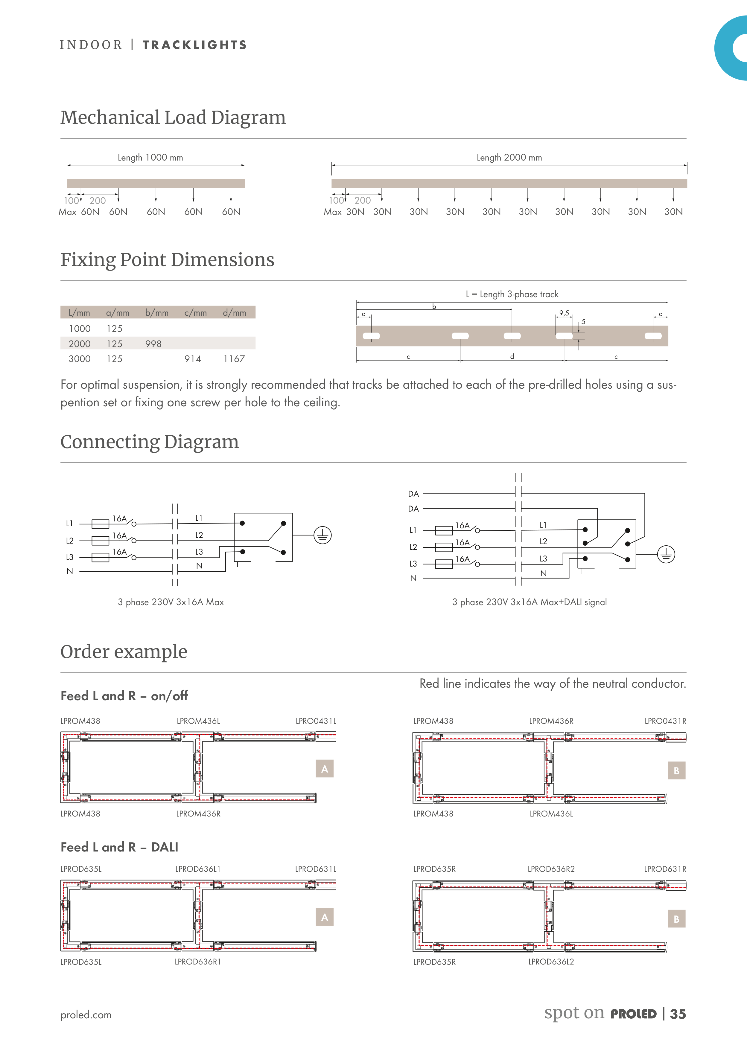
Mechanical Load Diagram
Fixing Point Dimensions
Connecting Diagram
Order example
Feed L and R – on/off
Red line indicates the way of the neutral conductor.
Feed L and R – DALI
For optimal suspension, it is strongly recommended that tracks be attached to each of the pre-drilled holes using a sus-
pention set or fixing one screw per hole to the ceiling.
L = Length 3-phase track
3 phase 230V 3x16A Max
3 phase 230V 3x16A Max+DALI signal
Length 1000 mm
Length 2000 mm
proled.com
I N D O O R | T R AC K L I G H T S
spot on
| 35