- VISTA ESTERNA -
A
CONTATTO SUPERIORE
TRASFORMATORE
al caricabatterie
220V
6
5
4
3
2
1
ROSSO
RED
NERO
BLACK
ALTO
TOP
BASSO
BOTTOM
1
220 V
3
4
2
B
CONTATTO INFERIORE
Stato porta
A
CONTATTO SUPERIORE
Comando Remoto
6
7
8
9
4
3
2
1
5
14
10
11
12
13
17
16
15
J1
J2
J3
positivo alimentazione
9/24VDC
negativo alimentazione
9/24VDC
NO
C
NO
C
C
NO
C
NO RL2
RL1
RL1
RL2
RL4
RL3
RL3
RL4
Relè posizione scrocco
Relè posizione catenacci
Relè posizione anta
Relè (impulso di 1 sec.) comando
apriporta motorizzato
pulsante "APRE"
9/24VAC/VDC
pulsante "CHIUDE"
9/24VAC/VDC
JP1
JP2
JP3
JP4
1
2
3
NO
C
NC
JP
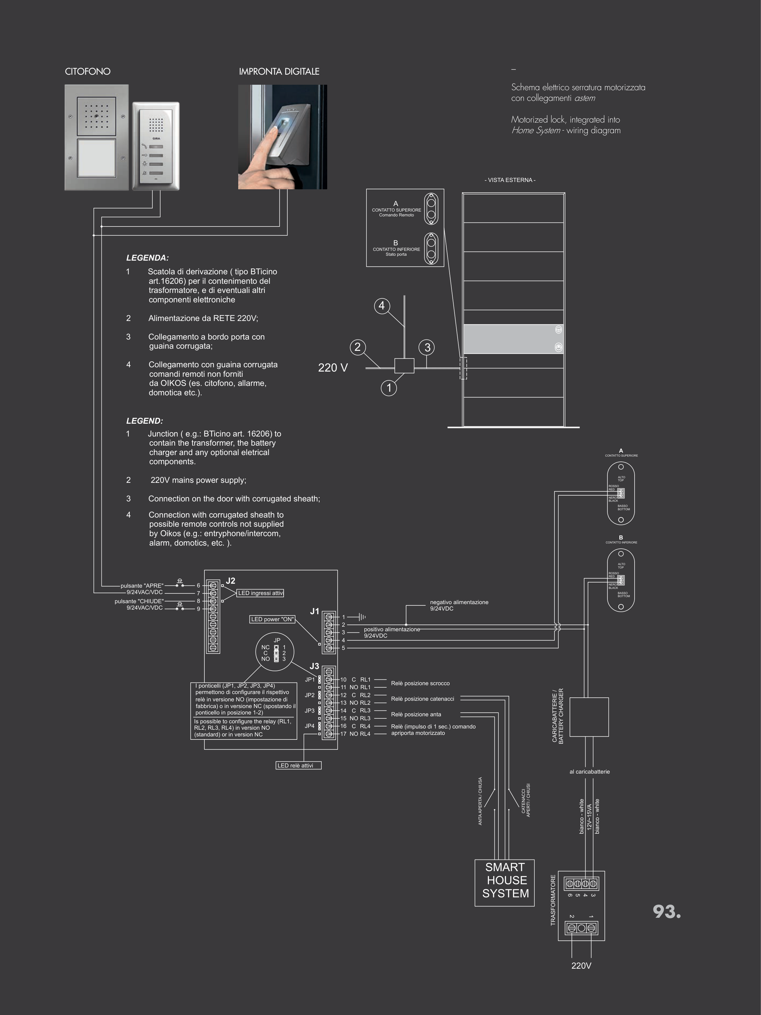
I ponticelli (JP1, JP2, JP3, JP4)
permettono di configurare il rispettivo
relè in versione NO (impostazione di
fabbrica) o in versione NC (spostando il
ponticello in posizione 1-2)
LED power "ON"
LED ingressi attivi
LED relè attivi
12V~15VA
bianco - white
bianco - white
CARICABATTERIE /
BATTERY CHARGER
BASSO
BOTTOM
ALTO
TOP
NERO
BLACK
ROSSO
RED
B
CONTATTO INFERIORE
SMART
HOUSE
SYSTEM
ANTA APERTA / CHIUSA
CATENACCI
APERTI / CHIUSI
Is possible to configure the relay (RL1,
RL2, RL3, RL4) in version NO
(standard) or in version NC
LEGENDA:
1
Scatola di derivazione ( tipo BTicino
art.16206) per il contenimento del
trasformatore, e di eventuali altri
componenti elettroniche
2
Alimentazione da RETE 220V;
3
Collegamento a bordo porta con
guaina corrugata;
4
Collegamento con guaina corrugata
comandi remoti non forniti
da OIKOS (es. citofono, allarme,
domotica etc.).
LEGEND:
1
Junction ( e.g.: BTicino art. 16206) to
contain the transformer, the battery
charger and any optional eletrical
components.
2
220V mains power supply;
3
Connection on the door with corrugated sheath;
4
Connection with corrugated sheath to
possible remote controls not supplied
by Oikos (e.g.: entryphone/intercom,
alarm, domotics, etc. ).
_
Schema elettrico serratura motorizzata
con collegamenti astem
Motorized lock, integrated into
Home System - wiring diagram
CITOFONO
IMPRONTA DIGITALE
93.