_ 344 _
www.luznegra.net
www.ecoled.net
ecoled by Luz Negra
www.luznegra.net
www.ecoled.net
+
+
+
+
-
-
-
-
Power
supply
Power
supply
Power
supply
Power
supply
Dimmer/Sensor
230V
230V
230V
230V
Input
Input
Input
Input
12V-24V
12V-24V
12V-24V
12V-24V
Output
Output
Output
Output
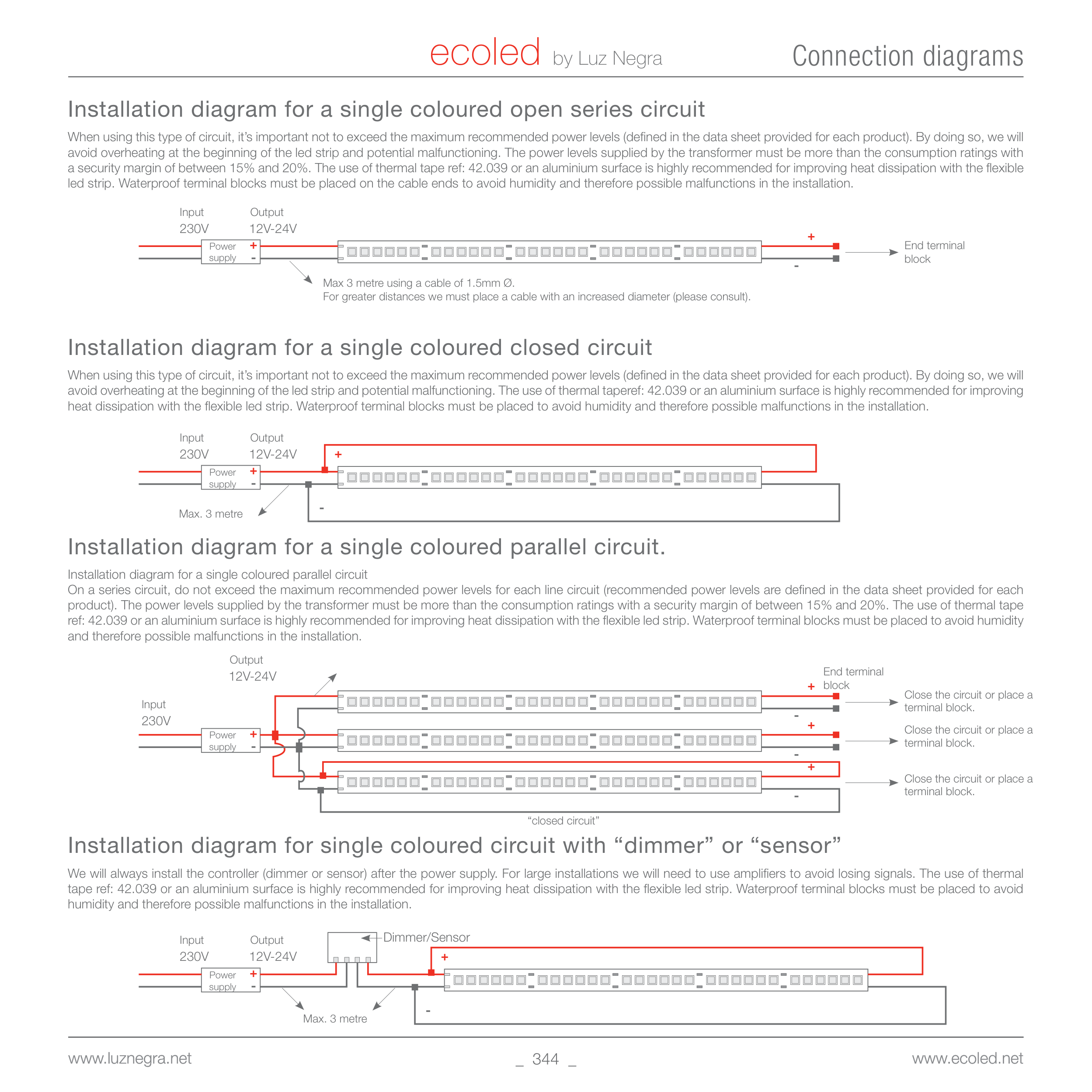
Installation diagram for a single coloured open series circuit
When using this type of circuit, it’s important not to exceed the maximum recommended power levels (defined in the data sheet provided for each product). By doing so, we will
avoid overheating at the beginning of the led strip and potential malfunctioning. The power levels supplied by the transformer must be more than the consumption ratings with
a security margin of between 15% and 20%. The use of thermal tape ref: 42.039 or an aluminium surface is highly recommended for improving heat dissipation with the flexible
led strip. Waterproof terminal blocks must be placed on the cable ends to avoid humidity and therefore possible malfunctions in the installation.
Installation diagram for a single coloured closed circuit
When using this type of circuit, it’s important not to exceed the maximum recommended power levels (defined in the data sheet provided for each product). By doing so, we will
avoid overheating at the beginning of the led strip and potential malfunctioning. The use of thermal taperef: 42.039 or an aluminium surface is highly recommended for improving
heat dissipation with the flexible led strip. Waterproof terminal blocks must be placed to avoid humidity and therefore possible malfunctions in the installation.
Installation diagram for a single coloured parallel circuit.
Installation diagram for a single coloured parallel circuit
On a series circuit, do not exceed the maximum recommended power levels for each line circuit (recommended power levels are defined in the data sheet provided for each
product). The power levels supplied by the transformer must be more than the consumption ratings with a security margin of between 15% and 20%. The use of thermal tape
ref: 42.039 or an aluminium surface is highly recommended for improving heat dissipation with the flexible led strip. Waterproof terminal blocks must be placed to avoid humidity
and therefore possible malfunctions in the installation.
Installation diagram for single coloured circuit with “dimmer” or “sensor”
We will always install the controller (dimmer or sensor) after the power supply. For large installations we will need to use amplifiers to avoid losing signals. The use of thermal
tape ref: 42.039 or an aluminium surface is highly recommended for improving heat dissipation with the flexible led strip. Waterproof terminal blocks must be placed to avoid
humidity and therefore possible malfunctions in the installation.
End terminal
block
Close the circuit or place a
terminal block.
Close the circuit or place a
terminal block.
Close the circuit or place a
terminal block.
-
-
+
+
+
+
+
+
-
-
-
-
Max. 3 metre
Max 3 metre using a cable of 1.5mm Ø.
For greater distances we must place a cable with an increased diameter (please consult).
Max. 3 metre
Connection diagrams
“closed circuit”
End terminal
block


