81033
81051
81066
81036
81054
81042
81048
80999
81057
81045
81063
81060
B
A
C
D
E
H
L
M
N
I
F
G
H
I
L
H
B
A
A
C
C
C
C
C
C
E
E
E
H
H
L
M
N
I
F
F
F
F
G
G
D
SX
DX
Track system configuration
Land line
TOP VIEW
Continuità della messa a terra
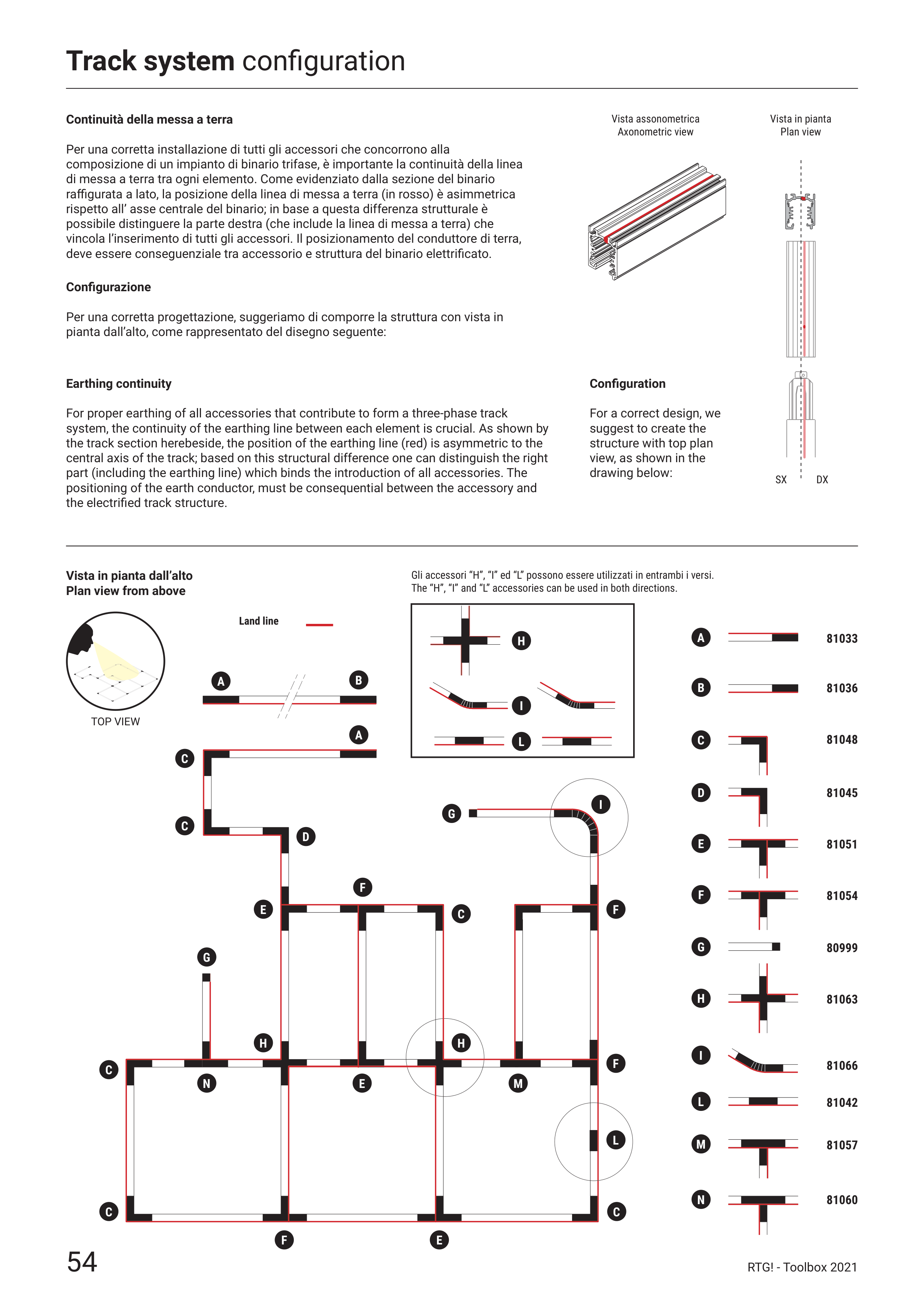
Per una corretta installazione di tutti gli accessori che concorrono alla
composizione di un impianto di binario trifase, è importante la continuità della linea
di messa a terra tra ogni elemento. Come evidenziato dalla sezione del binario
raffigurata a lato, la posizione della linea di messa a terra (in rosso) è asimmetrica
rispetto all’ asse centrale del binario; in base a questa differenza strutturale è
possibile distinguere la parte destra (che include la linea di messa a terra) che
vincola l’inserimento di tutti gli accessori. Il posizionamento del conduttore di terra,
deve essere conseguenziale tra accessorio e struttura del binario elettrificato.
Configurazione
Per una corretta progettazione, suggeriamo di comporre la struttura con vista in
pianta dall’alto, come rappresentato del disegno seguente:
Earthing continuity
For proper earthing of all accessories that contribute to form a three-phase track
system, the continuity of the earthing line between each element is crucial. As shown by
the track section herebeside, the position of the earthing line (red) is asymmetric to the
central axis of the track; based on this structural difference one can distinguish the right
part (including the earthing line) which binds the introduction of all accessories. The
positioning of the earth conductor, must be consequential between the accessory and
the electrified track structure.
Configuration
For a correct design, we
suggest to create the
structure with top plan
view, as shown in the
drawing below:
Gli accessori “H”, “I” ed “L” possono essere utilizzati in entrambi i versi.
The “H”, “I” and “L” accessories can be used in both directions.
Vista in pianta
Plan view
Vista assonometrica
Axonometric view
Vista in pianta dall’alto
Plan view from above
54
RTG! - Toolbox 2021


