201
Projectors
81033
81051
81066
81036
81054
81042
81048
80999
81057
81045
81063
81060
B
A
C
D
E
H
L
M
N
I
F
G
H
I
L
TOP VIEW
H
B
A
A
C
C
C
C
C
C
E
E
E
H
H
L
M
N
I
F
F
F
F
G
G
D
SX
DX
track system configuration
Earthing continuity
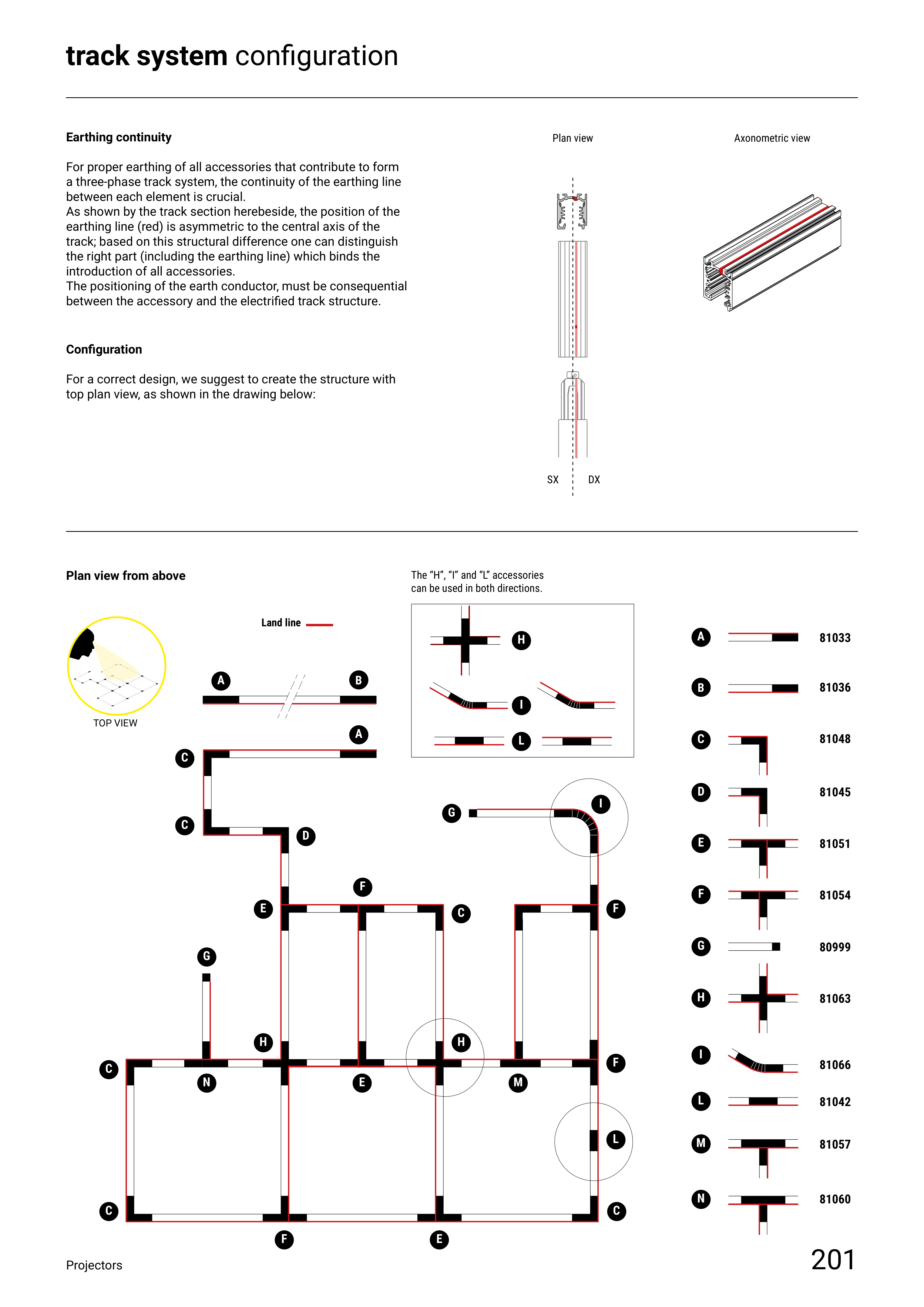
For proper earthing of all accessories that contribute to form
a three-phase track system, the continuity of the earthing line
between each element is crucial.
As shown by the track section herebeside, the position of the
earthing line (red) is asymmetric to the central axis of the
track; based on this structural difference one can distinguish
the right part (including the earthing line) which binds the
introduction of all accessories.
The positioning of the earth conductor, must be consequential
between the accessory and the electrified track structure.
Configuration
For a correct design, we suggest to create the structure with
top plan view, as shown in the drawing below:
Plan view from above
Plan view
Axonometric view
The “H”, “I” and “L” accessories
can be used in both directions.
Land line
back to index


