INSTALLATION INSTRUCTIONS
INSTRUCCIONES DE MONTAJE
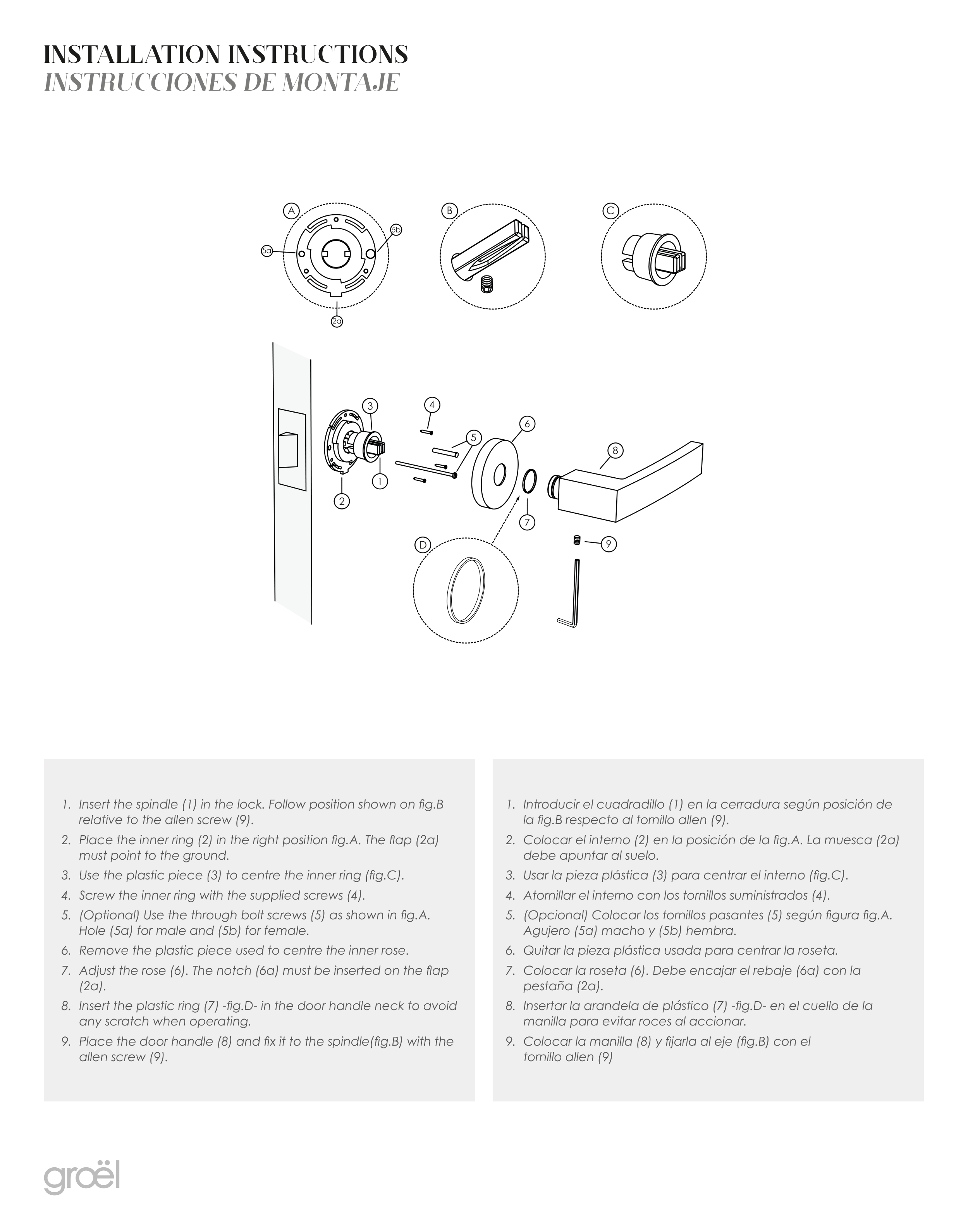
1. Insert the spindle (1) in the lock. Follow position shown on fig.B
relative to the allen screw (9).
2. Place the inner ring (2) in the right position fig.A. The flap (2a)
must point to the ground.
3. Use the plastic piece (3) to centre the inner ring (fig.C).
4. Screw the inner ring with the supplied screws (4).
5. (Optional) Use the through bolt screws (5) as shown in fig.A.
Hole (5a) for male and (5b) for female.
6. Remove the plastic piece used to centre the inner rose.
7. Adjust the rose (6). The notch (6a) must be inserted on the flap
(2a).
8. Insert the plastic ring (7) -fig.D- in the door handle neck to avoid
any scratch when operating.
9. Place the door handle (8) and fix it to the spindle(fig.B) with the
allen screw (9).
1. Introducir el cuadradillo (1) en la cerradura según posición de
la fig.B respecto al tornillo allen (9).
2. Colocar el interno (2) en la posición de la fig.A. La muesca (2a)
debe apuntar al suelo.
3. Usar la pieza plástica (3) para centrar el interno (fig.C).
4. Atornillar el interno con los tornillos suministrados (4).
5. (Opcional) Colocar los tornillos pasantes (5) según figura fig.A.
Agujero (5a) macho y (5b) hembra.
6. Quitar la pieza plástica usada para centrar la roseta.
7. Colocar la roseta (6). Debe encajar el rebaje (6a) con la
pestaña (2a).
8. Insertar la arandela de plástico (7) -fig.D- en el cuello de la
manilla para evitar roces al accionar.
9. Colocar la manilla (8) y fijarla al eje (fig.B) con el
tornillo allen (9)