629
60.3046
60.3039
60.3036
60.3016
60.3047
60.3028
60.3028
60.3016
(A)
1.
2.
(B)
(H)
(C)
(H)
(H)
(D)
(H)
60.3039
60.3038
60.3028
60.3051
60.3028
60.3028
60.3049
60.3028
(I)
(E)
(I)
(I)
(F)
(I)
60.3029
60.3047
60.3029
60.3029
60.3048
60.3029
3 - P H A S E N - S T R O M S C H I E N E N / T H R E E P H A S E T R A C K S
Beispiel / Example
Anmerkungen zur Montage
Bei der Montage der Schiene ist zunächst zu
bestimmen, auf welcher Seite die Erde liegen soll.
Demnach sind die jeweiligen Zubehöre zu benutzen. In
den folgenden Abbildungen zeigt die gestrichelte Linie
die Position der Erdung an.
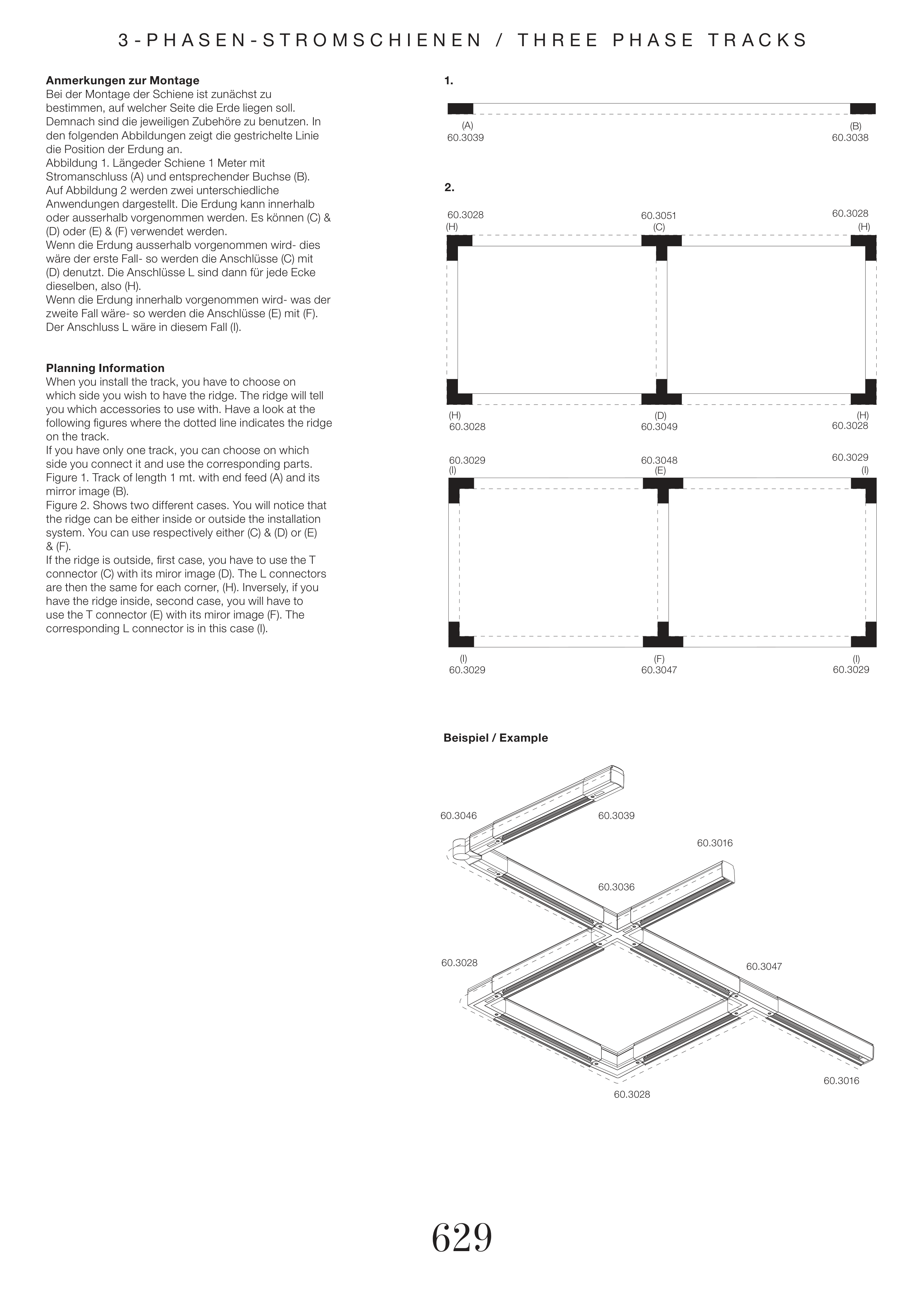
Abbildung 1. Längeder Schiene 1 Meter mit
Stromanschluss (A) und entsprechender Buchse (B).
Auf Abbildung 2 werden zwei unterschiedliche
Anwendungen dargestellt. Die Erdung kann innerhalb
oder ausserhalb vorgenommen werden. Es können (C) &
(D) oder (E) & (F) verwendet werden.
Wenn die Erdung ausserhalb vorgenommen wird- dies
wäre der erste Fall- so werden die Anschlüsse (C) mit
(D) denutzt. Die Anschlüsse L sind dann für jede Ecke
dieselben, also (H).
Wenn die Erdung innerhalb vorgenommen wird- was der
zweite Fall wäre- so werden die Anschlüsse (E) mit (F).
Der Anschluss L wäre in diesem Fall (I).
Planning Information
When you install the track, you have to choose on
which side you wish to have the ridge. The ridge will tell
you which accessories to use with. Have a look at the
following figures where the dotted line indicates the ridge
on the track.
If you have only one track, you can choose on which
side you connect it and use the corresponding parts.
Figure 1. Track of length 1 mt. with end feed (A) and its
mirror image (B).
Figure 2. Shows two different cases. You will notice that
the ridge can be either inside or outside the installation
system. You can use respectively either (C) & (D) or (E)
& (F).
If the ridge is outside, first case, you have to use the T
connector (C) with its miror image (D). The L connectors
are then the same for each corner, (H). Inversely, if you
have the ridge inside, second case, you will have to
use the T connector (E) with its miror image (F). The
corresponding L connector is in this case (I).


