73
TECHNICAL DATA
EXAMPLE OF USE FD011F SOCKET
OR "ECOCOMPACT" KIT TO CREATE
THE TV / SATELLITE NETWORK
EXAMPLE OF USE FD506F AND FD002F SOCKETS
TO ESTABLISH A "WATERFALL" TV NETWORK
AND THE DIRECT CONNECTION OF TV SATELLITE
EXAMPLE OF USING THE FD220F PLUG BASE TO
CREATE A "WATERFALL" TV / SATELLITE NETWORK
WITH AN IF-IF CABLE
EXAMPLE OF USE OF FD010F PLUG
BASES TO CREATE A "STAR" TYPE
TV / SATELLITE NETWORK
FD010F
TV
SAT
DEMIX
FD010F
TV
SAT
DEMIX
FD010F
TV
SAT
DEMIX
FD010F
TV
SAT
DEMIX
FD010F
TV
SAT
DEMIX
Multiswitches
TV Receiver
FD220F/14
FD220F/10
FD220F/6
FD220F/3
FD220F/18
TV
SAT
DEMIX
TV
SAT
DEMIX
TV
SAT
DEMIX
TV
SAT
DEMIX
TV
SAT
DEMIX
FD013F/3
TV
SAT
DIPECT
SAT Receiver
TV Receiver
FD011F
“ECOCOMPACT”
TV
SAT
TV Receiver
FD002F
FD506F/6
FD506F/10
FD506F/14
FD506F/18
TV Receiver
TV & SAT signal
SAT signal
TV signal
MECHANISM CONNECTION DIAGRAMS FOR POWER TV SOCKET OUTLETS
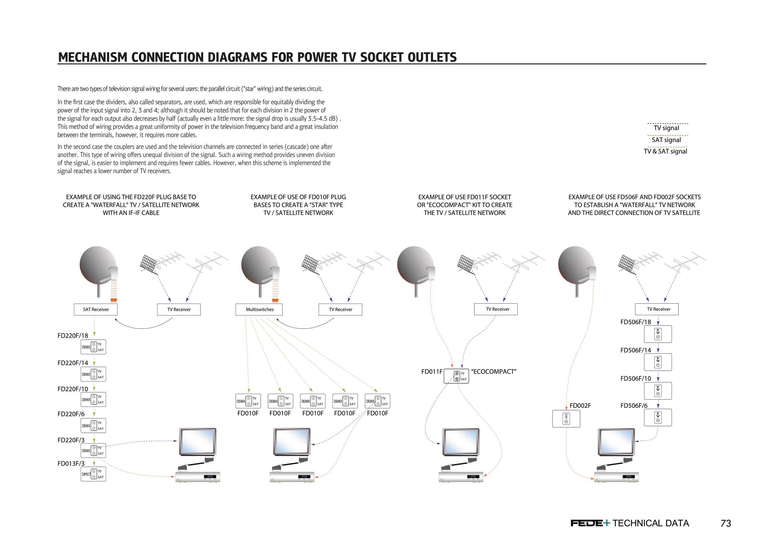
There are two types of television signal wiring for several users: the parallel circuit ("star" wiring) and the series circuit.
In the first case the dividers, also called separators, are used, which are responsible for equitably dividing the
power of the input signal into 2, 3 and 4; although it should be noted that for each division in 2 the power of
the signal for each output also decreases by half (actually even a little more: the signal drop is usually 3.5-4.5 dB) .
This method of wiring provides a great uniformity of power in the television frequency band and a great insulation
between the terminals, however, it requires more cables.
In the second case the couplers are used and the television channels are connected in series (cascade) one aſter
another. This type of wiring offers unequal division of the signal. Such a wiring method provides uneven division
of the signal, is easier to implement and requires fewer cables. However, when this scheme is implemented the
signal reaches a lower number of TV receivers.


