USB interface
SYSTEM DEVICES
Description
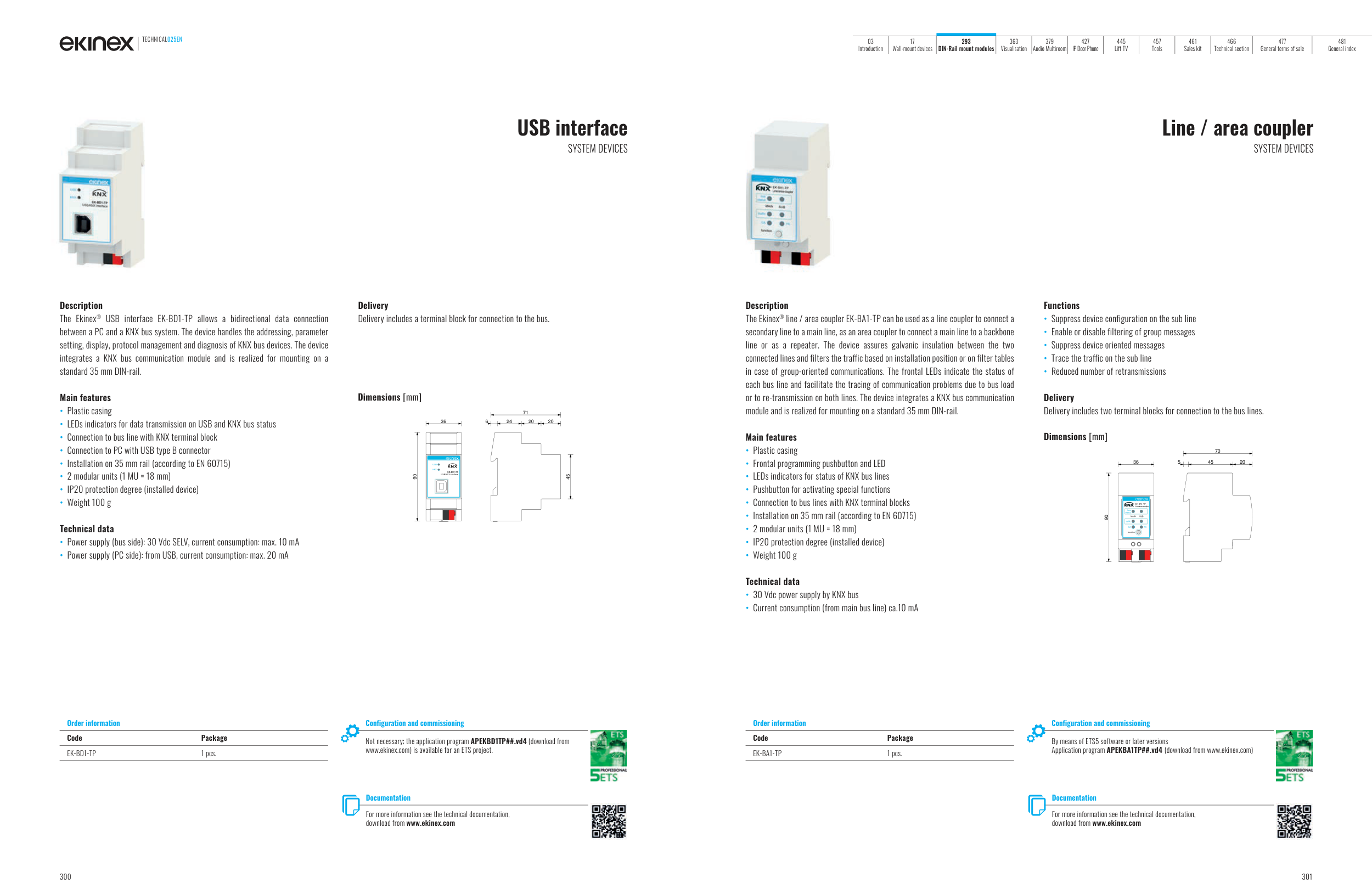
The Ekinex® USB interface EK-BD1-TP allows a bidirectional data connection
between a PC and a KNX bus system. The device handles the addressing, parameter
setting, display, protocol management and diagnosis of KNX bus devices. The device
integrates a KNX bus communication module and is realized for mounting on a
standard 35 mm DIN-rail.
Main features
• Plastic casing
• LEDs indicators for data transmission on USB and KNX bus status
• Connection to bus line with KNX terminal block
• Connection to PC with USB type B connector
• Installation on 35 mm rail (according to EN 60715)
• 2 modular units (1 MU = 18 mm)
• IP20 protection degree (installed device)
• Weight 100 g
Technical data
• Power supply (bus side): 30 Vdc SELV, current consumption: max. 10 mA
• Power supply (PC side): from USB, current consumption: max. 20 mA
Delivery
Delivery includes a terminal block for connection to the bus.
Order information
Code
Package
EK-BD1-TP
1 pcs.
Configuration and commissioning
Not necessary; the application program APEKBD1TP##.vd4 (download from
www.ekinex.com) is available for an ETS project.
Documentation
For more information see the technical documentation,
download from www.ekinex.com
Dimensions [mm]
36
6
24
20
20
71
45
90
USB
KNX
EK-BD1-TP
USB/KNX interface
Line / area coupler
SYSTEM DEVICES
Description
The Ekinex® line / area coupler EK-BA1-TP can be used as a line coupler to connect a
secondary line to a main line, as an area coupler to connect a main line to a backbone
line or as a repeater. The device assures galvanic insulation between the two
connected lines and filters the traffic based on installation position or on filter tables
in case of group-oriented communications. The frontal LEDs indicate the status of
each bus line and facilitate the tracing of communication problems due to bus load
or to re-transmission on both lines. The device integrates a KNX bus communication
module and is realized for mounting on a standard 35 mm DIN-rail.
Main features
• Plastic casing
• Frontal programming pushbutton and LED
• LEDs indicators for status of KNX bus lines
• Pushbutton for activating special functions
• Connection to bus lines with KNX terminal blocks
• Installation on 35 mm rail (according to EN 60715)
• 2 modular units (1 MU = 18 mm)
• IP20 protection degree (installed device)
• Weight 100 g
Technical data
• 30 Vdc power supply by KNX bus
• Current consumption (from main bus line) ca.10 mA
Functions
• Suppress device configuration on the sub line
• Enable or disable filtering of group messages
• Suppress device oriented messages
• Trace the traffic on the sub line
• Reduced number of retransmissions
Delivery
Delivery includes two terminal blocks for connection to the bus lines.
Order information
Code
Package
EK-BA1-TP
1 pcs.
Configuration and commissioning
By means of ETS5 software or later versions
Application program APEKBA1TP##.vd4 (download from www.ekinex.com)
Documentation
For more information see the technical documentation,
download from www.ekinex.com
Dimensions [mm]
90
36
5
45
20
70
bus
status
traffic
GA
function
PA
R EK-BA1-TP
MAIN
SUB
Line/area coupler
TECHNICAL025EN
300
301
03
Introduction
17
Wall-mount devices
293
DIN-Rail mount modules
363
Visualisation
379
Audio Multiroom
427
IP Door Phone
445
Lift TV
457
Tools
461
Sales kit
466
Technical section
477
General terms of sale
481
General index