Device addressing
The bus is a shared communication medium and each connected device must be
exclusively distinguished from all others. The ETS® program takes care of that by
assigning a physical address to each device; the address is represented in the form
“area.line.device”. Thanks to that, the topology of the entire system is mirrored
into the devices’ physical addresses, making it easy to locate a device in the whole
topology, by simply knowing its physical address. For instance:
3.5.12 is the physical address of the bus device number 12, installed
along line 5 in area 3
7.11.4 is the physical address of bus device number 4 on line 11 in area 7
A line coupler connects a secondary line to the backbone line; the device forms an
integral part of the secondary line and conventionally assumes the device number
“0”. The physical address of a line coupler can be, for instance:
3.5.0 is the physical address of the coupler connecting the secondary
line n. 5 to the main line of area 3
The area coupler connects an area’s main line to the backbone line; the device is part
of the main line and conventionally assumes device number “0” and line number “0”.
The physical address of an area coupler is, for example:
3.0.0 is the physical address of the coupler connecting the main line of
area 3 to the system’s backbone line
KNX technology
TECHNICAL SECTION
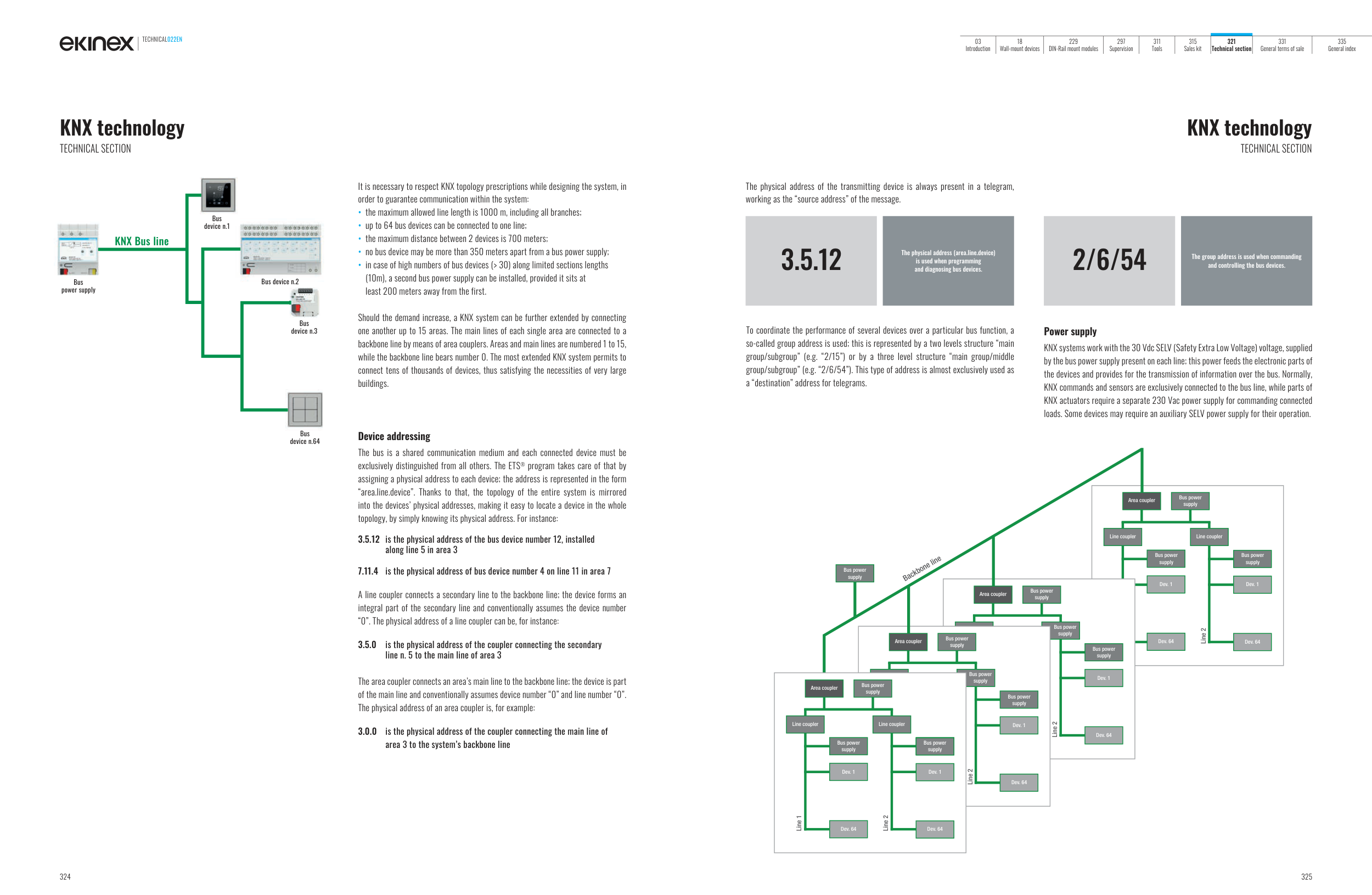
It is necessary to respect KNX topology prescriptions while designing the system, in
order to guarantee communication within the system:
• the maximum allowed line length is 1000 m, including all branches;
• up to 64 bus devices can be connected to one line;
• the maximum distance between 2 devices is 700 meters;
• no bus device may be more than 350 meters apart from a bus power supply;
• in case of high numbers of bus devices (> 30) along limited sections lengths
(10m), a second bus power supply can be installed, provided it sits at
least 200 meters away from the first.
Should the demand increase, a KNX system can be further extended by connecting
one another up to 15 areas. The main lines of each single area are connected to a
backbone line by means of area couplers. Areas and main lines are numbered 1 to 15,
while the backbone line bears number 0. The most extended KNX system permits to
connect tens of thousands of devices, thus satisfying the necessities of very large
buildings.
KNX Bus line
Bus
power supply
Bus
device n.64
Bus
device n.1
Bus
device n.3
Bus device n.2
KNX technology
TECHNICAL SECTION
The physical address of the transmitting device is always present in a telegram,
working as the “source address” of the message.
The physical address (area.line.device)
is used when programming
and diagnosing bus devices.
3.5.12
To coordinate the performance of several devices over a particular bus function, a
so-called group address is used; this is represented by a two levels structure “main
group/subgroup” (e.g. “2/15”) or by a three level structure “main group/middle
group/subgroup” (e.g. “2/6/54”). This type of address is almost exclusively used as
a “destination” address for telegrams.
Power supply
KNX systems work with the 30 Vdc SELV (Safety Extra Low Voltage) voltage, supplied
by the bus power supply present on each line; this power feeds the electronic parts of
the devices and provides for the transmission of information over the bus. Normally,
KNX commands and sensors are exclusively connected to the bus line, while parts of
KNX actuators require a separate 230 Vac power supply for commanding connected
loads. Some devices may require an auxiliary SELV power supply for their operation.
The group address is used when commanding
and controlling the bus devices.
2/6/54
Line #1
Line #2
Area coupler
Bus power
supply
Accoppiatore di Line
Bus power
supply
Bus power supply
Dev. #1
Dev. #64
Dev. 1
Dev. 64
Line 2
Line 2
Accoppiatore di Line
Dev. #1
Dev. #64
Line 2
Area coupler
Bus power
supply
Line coupler
Line coupler
Dev. 1
Dev. 64
Bus power supply
Dev. #1
Dev. #64
Line 2
Line 1
Bus power
supply
Bus power
supply
Bus power
supply
Bus power
supply
Backbone line
Dev. 1
Dev. 64
Area coupler
Bus power
supply
Line coupler
Line coupler
Dev. 1
Dev. 64
Dev. 1
Dev. 64
Bus power
supply
Area coupler
Bus power
supply
Dev. 1
Dev. 64
Bus power
supply
Bus power
supply
Bus power
supply
TECHNICAL022EN
324
325
03
Introduction
18
Wall-mount devices
229
DIN-Rail mount modules
297
Supervision
311
Tools
315
Sales kit
321
Technical section
331
General terms of sale
335
General index