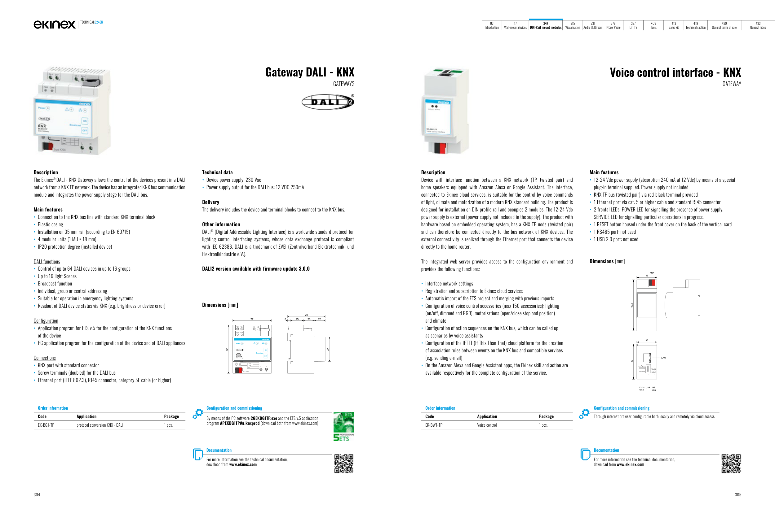
Description
The Ekinex® DALI - KNX Gateway allows the control of the devices present in a DALI
network from a KNX TP network. The device has an integrated KNX bus communication
module and integrates the power supply stage for the DALI bus.
Main features
• Connection to the KNX bus line with standard KNX terminal block
• Plastic casing
• Installation on 35 mm rail (according to EN 60715)
• 4 modular units (1 MU = 18 mm)
• IP20 protection degree (installed device)
DALI functions
• Control of up to 64 DALI devices in up to 16 groups
• Up to 16 light Scenes
• Broadcast function
• Individual, group or central addressing
• Suitable for operation in emergency lighting systems
• Readout of DALI device status via KNX (e.g. brightness or device error)
Configuration
• Application program for ETS v.5 for the configuration of the KNX functions
of the device
• PC application program for the configuration of the device and of DALI appliances
Connections
• KNX port with standard connector
• Screw terminals (doubled) for the DALI bus
• Ethernet port (IEEE 802.3), RJ45 connector, category 5E cable (or higher)
Technical data
• Device power supply: 230 Vac
• Power supply output for the DALI bus: 12 VDC 250mA
Delivery
The delivery includes the device and terminal blocks to connect to the KNX bus.
Other information
DALI® (Digital Addressable Lighting Interface) is a worldwide standard protocol for
lighting control interfacing systems, whose data exchange protocol is compliant
with IEC 62386. DALI is a trademark of ZVEI (Zentralverband Elektrotechnik- und
Elektronikindustrie e.V.).
DALI2 version available with firmware update 3.0.0
Dimensions [mm]
72
70
5
25
20
20
45
90
3
4
5
6
1
2
L
N
bus KNX
Dev.
Line
Area
PWR
COM
DA+
DA-
DA+
DA-
Gateway DALI - KNX
GATEWAYS
Order information
Code
Application
Package
EK-BG1-TP
protocol conversion KNX - DALI
1 pcs.
Documentation
For more information see the technical documentation,
download from www.ekinex.com
Configuration and commissioning
By means of the PC software CGEKBG1TP.exe and the ETS v.5 application
program APEKBG1TP##.knxprod (download both from www.ekinex.com)
Documentation
For more information see the technical documentation,
download from www.ekinex.com
Voice control interface - KNX
GATEWAY
Order information
Code
Application
Package
EK-BW1-TP
Voice control
1 pcs.
Configuration and commissioning
Through internet browser configurable both locally and remotely via cloud access.
Description
Device with interface function between a KNX network (TP, twisted pair) and
home speakers equipped with Amazon Alexa or Google Assistant. The interface,
connected to Ekinex cloud services, is suitable for the control by voice commands
of light, climate and motorization of a modern KNX standard building. The product is
designed for installation on DIN profile rail and occupies 2 modules. The 12-24 Vdc
power supply is external (power supply not included in the supply). The product with
hardware based on embedded operating system, has a KNX TP node (twisted pair)
and can therefore be connected directly to the bus network of KNX devices. The
external connectivity is realized through the Ethernet port that connects the device
directly to the home router.
The integrated web server provides access to the configuration environment and
provides the following functions:
• Interface network settings
• Registration and subscription to Ekinex cloud services
• Automatic import of the ETS project and merging with previous imports
• Configuration of voice control accessories (max 150 accessories): lighting
(on/off, dimmed and RGB), motorizations (open/close stop and position)
and climate
• Configuration of action sequences on the KNX bus, which can be called up
as scenarios by voice assistants
• Configuration of the IFTTT (If This Than That) cloud platform for the creation
of association rules between events on the KNX bus and compatible services
(e.g. sending e-mail)
• On the Amazon Alexa and Google Assistant apps, the Ekinex skill and action are
available respectively for the complete configuration of the service.
Main features
• 12-24 Vdc power supply (absorption 240 mA at 12 Vdc) by means of a special
plug-in terminal supplied. Power supply not included
• KNX TP bus (twisted pair) via red-black terminal provided
• 1 Ethernet port via cat. 5 or higher cable and standard RJ45 connector
• 2 frontal LEDs: POWER LED for signalling the presence of power supply;
SERVICE LED for signalling particular operations in progress.
• 1 RESET button housed under the front cover on the back of the vertical card
• 1 RS485 port: not used
• 1 USB 2.0 port: not used
Dimensions [mm]
LAN
USB
62
90.5
36
12-24
VDC
KNX
RS
485
36
TECHNICAL024EN
304
305
03
Introduction
17
Wall-mount devices
247
DIN-Rail mount modules
315
Visualisation
331
Audio Multiroom
379
IP Door Phone
397
Lift TV
409
Tools
413
Sales kit
419
Technical section
429
General terms of sale
433
General index