Gateway M-Bus - KNX
GATEWAYS
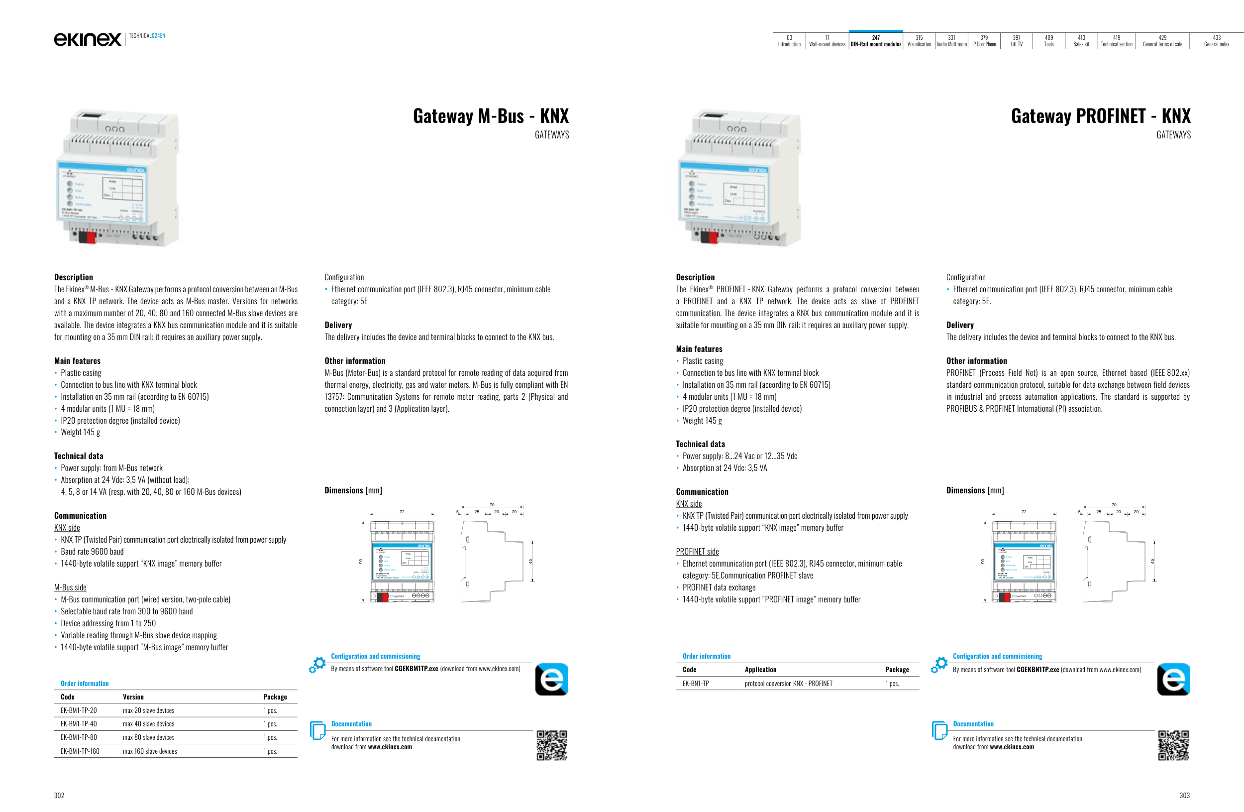
Description
The Ekinex® M-Bus - KNX Gateway performs a protocol conversion between an M-Bus
and a KNX TP network. The device acts as M-Bus master. Versions for networks
with a maximum number of 20, 40, 80 and 160 connected M-Bus slave devices are
available. The device integrates a KNX bus communication module and it is suitable
for mounting on a 35 mm DIN rail; it requires an auxiliary power supply.
Main features
• Plastic casing
• Connection to bus line with KNX terminal block
• Installation on 35 mm rail (according to EN 60715)
• 4 modular units (1 MU = 18 mm)
• IP20 protection degree (installed device)
• Weight 145 g
Technical data
• Power supply: from M-Bus network
• Absorption at 24 Vdc: 3,5 VA (without load);
4, 5, 8 or 14 VA (resp. with 20, 40, 80 or 160 M-Bus devices)
Communication
KNX side
• KNX TP (Twisted Pair) communication port electrically isolated from power supply
• Baud rate 9600 baud
• 1440-byte volatile support “KNX image” memory buffer
M-Bus side
• M-Bus communication port (wired version, two-pole cable)
• Selectable baud rate from 300 to 9600 baud
• Device addressing from 1 to 250
• Variable reading through M-Bus slave device mapping
• 1440-byte volatile support “M-Bus image” memory buffer
Configuration
• Ethernet communication port (IEEE 802.3), RJ45 connector, minimum cable
category: 5E
Delivery
The delivery includes the device and terminal blocks to connect to the KNX bus.
Other information
M-Bus (Meter-Bus) is a standard protocol for remote reading of data acquired from
thermal energy, electricity, gas and water meters. M-Bus is fully compliant with EN
13757: Communication Systems for remote meter reading, parts 2 (Physical and
connection layer) and 3 (Application layer).
Order information
Code
Version
Package
EK-BM1-TP-20
max 20 slave devices
1 pcs.
EK-BM1-TP-40
max 40 slave devices
1 pcs.
EK-BM1-TP-80
max 80 slave devices
1 pcs.
EK-BM1-TP-160
max 160 slave devices
1 pcs.
Documentation
For more information see the technical documentation,
download from www.ekinex.com
Configuration and commissioning
By means of software tool CGEKBM1TP.exe (download from www.ekinex.com)
Dimensions [mm]
72
5
25
20
20
70
45
90
ETHERNET
M-BUS
POWER S.
+
1
0V
+V
-
4
3
2
KNX
M-Bus
Device state
8...24 Vac
12...35 Vdc
Dev.
Line
Area
Failure
bus KNX
EK-BM1-TP-160
M-Bus Master
/ KNX TP Converter 160 Dev.
Gateway PROFINET - KNX
GATEWAYS
Description
The Ekinex® PROFINET - KNX Gateway performs a protocol conversion between
a PROFINET and a KNX TP network. The device acts as slave of PROFINET
communication. The device integrates a KNX bus communication module and it is
suitable for mounting on a 35 mm DIN rail; it requires an auxiliary power supply.
Main features
• Plastic casing
• Connection to bus line with KNX terminal block
• Installation on 35 mm rail (according to EN 60715)
• 4 modular units (1 MU = 18 mm)
• IP20 protection degree (installed device)
• Weight 145 g
Technical data
• Power supply: 8...24 Vac or 12...35 Vdc
• Absorption at 24 Vdc: 3,5 VA
Communication
KNX side
• KNX TP (Twisted Pair) communication port electrically isolated from power supply
• 1440-byte volatile support “KNX image” memory buffer
PROFINET side
• Ethernet communication port (IEEE 802.3), RJ45 connector, minimum cable
category: 5E.Communication PROFINET slave
• PROFINET data exchange
• 1440-byte volatile support “PROFINET image” memory buffer
Configuration
• Ethernet communication port (IEEE 802.3), RJ45 connector, minimum cable
category: 5E.
Delivery
The delivery includes the device and terminal blocks to connect to the KNX bus.
Other information
PROFINET (Process Field Net) is an open source, Ethernet based (IEEE 802.xx)
standard communication protocol, suitable for data exchange between field devices
in industrial and process automation applications. The standard is supported by
PROFIBUS & PROFINET International (PI) association.
Order information
Code
Application
Package
EK-BN1-TP
protocol conversion KNX - PROFINET
1 pcs.
Configuration and commissioning
By means of software tool CGEKBN1TP.exe (download from www.ekinex.com)
Documentation
For more information see the technical documentation,
download from www.ekinex.com
Dimensions [mm]
72
5
25
20
20
70
45
90
bus KNX
1
2
8...24 Vac
+V
0V
POWER S.
12...35 Vdc
ETHERNET
Dev.
Line
Area
KNX
PROFINET
Device state
EK-BN1-TP
PROFINET
/ KNX TP Converter
Failure
TECHNICAL024EN
302
303
03
Introduction
17
Wall-mount devices
247
DIN-Rail mount modules
315
Visualisation
331
Audio Multiroom
379
IP Door Phone
397
Lift TV
409
Tools
413
Sales kit
419
Technical section
429
General terms of sale
433
General index