80
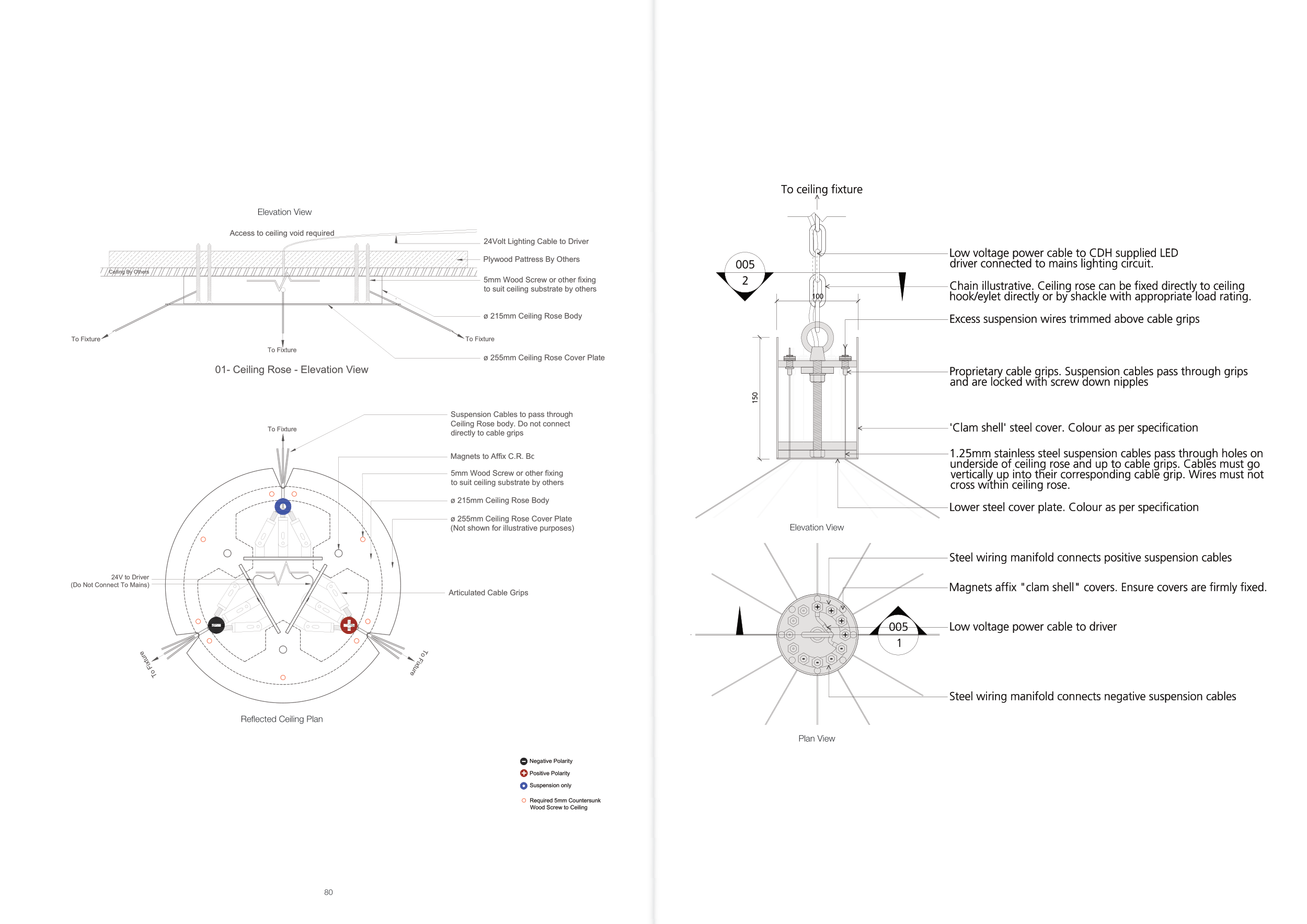
Elevation View
Reflected Ceiling Plan
Date:
07/03/2018
Project:
CDH Standard Details
Drawing No:
DR-CDH-002-REV B
Product name:
Ceiling Rose Small Typical Installation
Contact CDH for more details
Scale: 1:2 @ A3 Drawn by: RMO
Drivers available in all dimming
protocols
02- Ceiling Rose - Reflected Ceiling Plan
5mm Wood Screw or other fixing
to suit ceiling substrate by others
ø 215mm Ceiling Rose Body
Required 5mm Countersunk
Wood Screw to Ceiling
Ceiling By Others
5mm Wood Screw or other fixing
to suit ceiling substrate by others
ø 215mm Ceiling Rose Body
Articulated Cable Grips
ø 255mm Ceiling Rose Cover Plate
01- Ceiling Rose - Elevation View
24Volt Lighting Cable to Driver
Plywood Pattress By Others
Access to ceiling void required
24V to Driver
(Do Not Connect To Mains)
ø 255mm Ceiling Rose Cover Plate
(Not shown for illustrative purposes)
To Fixture
Notes:
Fix ceiling rose assembly
to ceiling with coloured
dots pointing downward.
Make certain that ceiling is capable
of supporting the weight of the entire
light, it is recommended that you
seek the advice of a structural engineer
or construction professional.
The appropriate fixing will vary
depending on ceiling substrate
therefore these have not been supplied,
use an appropriate fixing
to suit your situation.
This should carried out by a suitably
qualified electrician. Do not turn on
the power.
Ensure ceiling rose cover plate is firmly
fixed and not obstructed by protruding
screw heads.
To Fixture
To Fixture
To Fixture
Suspension Cables to pass through
Ceiling Rose body. Do not connect
directly to cable grips
To Fixture
To Fixture
Suspension only
Positive Polarity
Negative Polarity
Magnets to Affix C.R. Body to Cover Plate
Elevation View
Plan View


