10
1
2
2
3
1
4
5
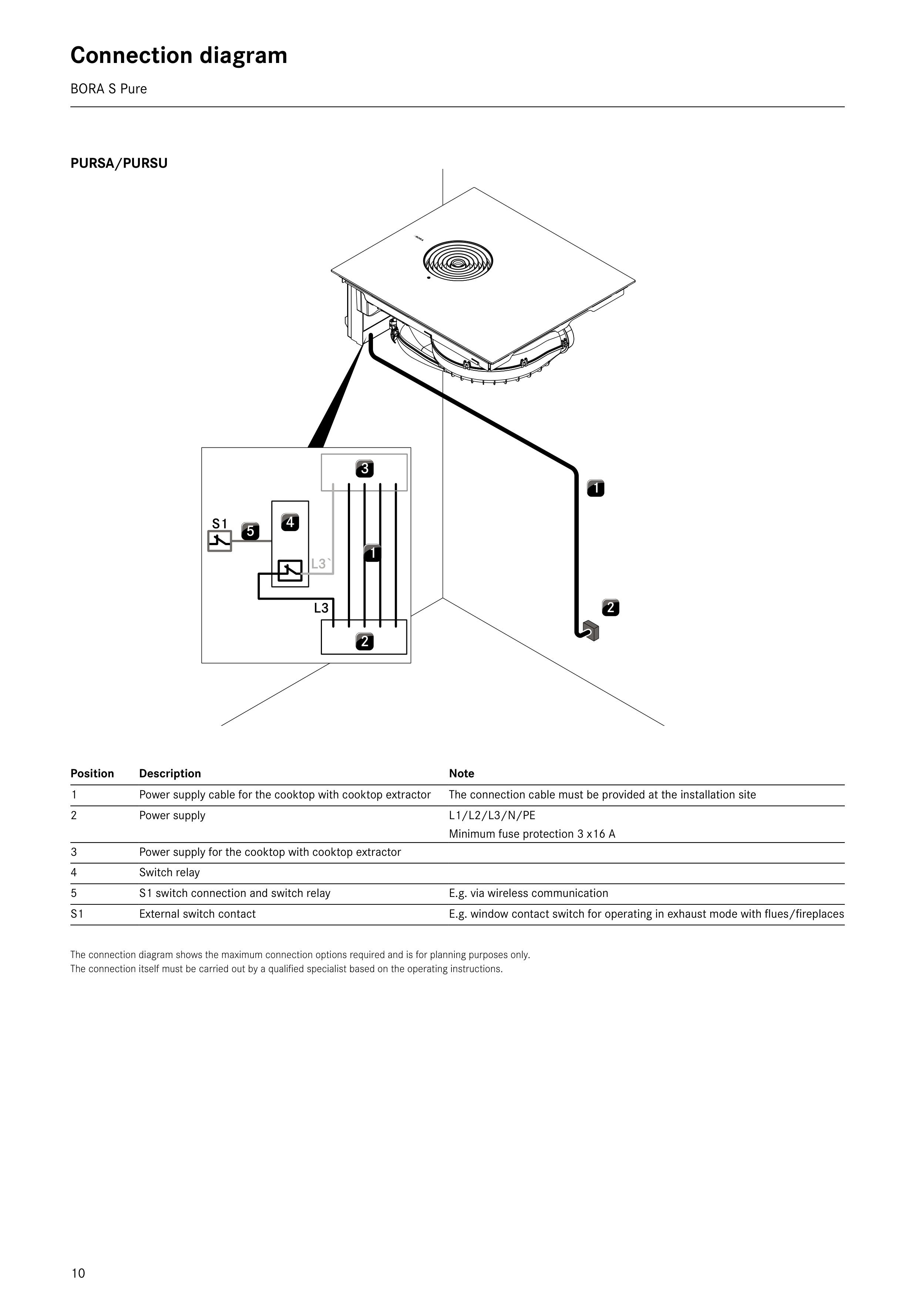
Connection diagram
BORA S Pure
The connection diagram shows the maximum connection options required and is for planning purposes only.
The connection itself must be carried out by a qualified specialist based on the operating instructions.
PURSA/PURSU
Position
Description
Note
1
Power supply cable for the cooktop with cooktop extractor
The connection cable must be provided at the installation site
2
Power supply
L1/L2/L3/N/PE
Minimum fuse protection 3 x16 A
3
Power supply for the cooktop with cooktop extractor
4
Switch relay
5
S1 switch connection and switch relay
E.g. via wireless communication
S1
External switch contact
E.g. window contact switch for operating in exhaust mode with flues/fireplaces