lx
8
4
2
1
0,5
0,2
m
0
2
4
6
8
10
12
14
16
18
20
6
4
2
0
8
77910
LED
H = 4,0 m
720
cd/klm
30°
77858
C 180 - C0
C 195 - C15
C 270 - C90
60°
30°
0°
30°
60°
cd/klm
500
1000
77584
ß= 28°/92°
¯E
lx
84503
LED
m
640
480
320
160
4
0
4
8
800
2
6
10
14
18
60°
30°
0°
30°
60°
cd/klm
600
1200
84503
ß= 27°/76°
Lighting technology · Basics · Planning
Good planning work is required to perform lighting applications. The BEGA catalogue contains a lot of information required for this, e.g. light
distribution curves, illumination and isolux diagrams. We have explained the basic information required on this page. We have also provided
luminaire lighting data and calculation programs on our website at www.bega.com. The BEGA lighting technology department can plan your
lighting systems according to your requirements. Our proposals are factual and take account of design requirements.
Fig. 1
Fig. 2
Illumination diagrams for floodlights (Fig. 3) specify the dimensions of the area limited by the two half beam angles (Fig. 4) and the average
illuminance of this area, depending on the distance. Using the parameters floodlights area horizontal axis it is possible to read off:
the height (continuous line, C 0 - C 180 ß = 27°) and the width (dotted line, C270- C90 ß=76°) of the limited area on the vertical axis
on the right
the average degree of illuminance (parabola) in lx on the vertical axis on the left
Example: At a distance of 12m, the half beam angles of the floodlight 84 503 limit an area of 5m in height and 15m wide.
The average degree of illuminance on this area is 240lx.
Uniform illumination can be obtained if the distances between the floodlights correspond to the width of the area limited by the half beam angles.
When a façade is illuminated from the ground, only about 1�3 of the specified illuminance can be achieved.
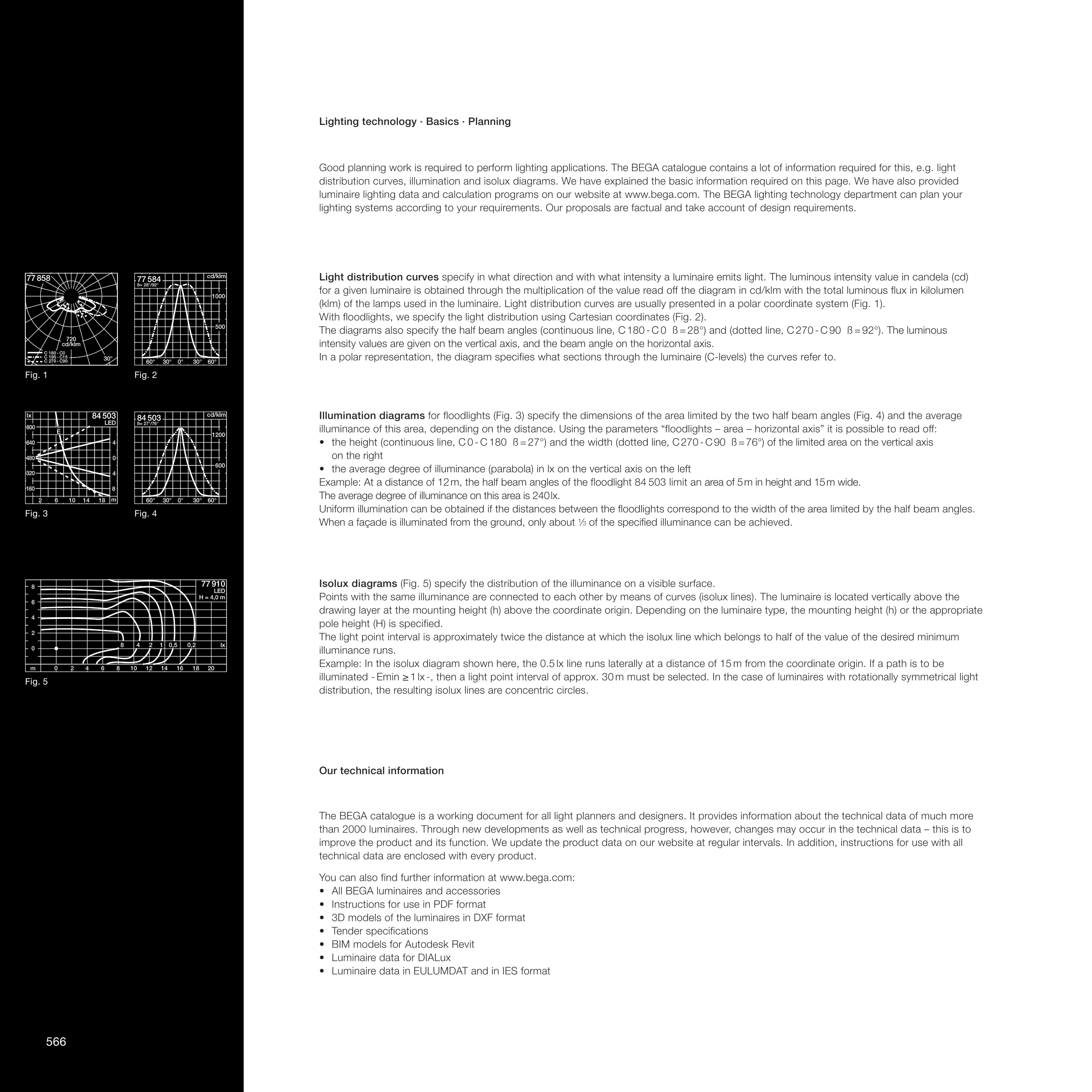
Isolux diagrams (Fig. 5) specify the distribution of the illuminance on a visible surface.
Points with the same illuminance are connected to each other by means of curves (isolux lines). The luminaire is located vertically above the
drawing layer at the mounting height (h) above the coordinate origin. Depending on the luminaire type, the mounting height (h) or the appropriate
pole height (H) is specified.
The light point interval is approximately twice the distance at which the isolux line which belongs to half of the value of the desired minimum
illuminance runs.
Example: In the isolux diagram shown here, the 0.5 lx line runs laterally at a distance of 15 m from the coordinate origin. If a path is to be
illuminated - Emin ≥ 1 lx -, then a light point interval of approx. 30 m must be selected. In the case of luminaires with rotationally symmetrical light
distribution, the resulting isolux lines are concentric circles.
Fig. 3
Fig. 4
Fig. 5
Light distribution curves specify in what direction and with what intensity a luminaire emits light. The luminous intensity value in candela (cd)
for a given luminaire is obtained through the multiplication of the value read off the diagram in cd/klm with the total luminous flux in kilolumen
(klm) of the lamps used in the luminaire. Light distribution curves are usually presented in a polar coordinate system (Fig. 1).
With floodlights, we specify the light distribution using Cartesian coordinates (Fig. 2).
The diagrams also specify the half beam angles (continuous line, C 180 - C 0 ß = 28°) and (dotted line, C 270 - C 90 ß = 92°). The luminous
intensity values are given on the vertical axis, and the beam angle on the horizontal axis.
In a polar representation, the diagram specifies what sections through the luminaire (C-levels) the curves refer to.
The BEGA catalogue is a working document for all light planners and designers. It provides information about the technical data of much more
than 2000 luminaires. Through new developments as well as technical progress, however, changes may occur in the technical data this is to
improve the product and its function. We update the product data on our website at regular intervals. In addition, instructions for use with all
technical data are enclosed with every product.
You can also find further information at www.bega.com:
All BEGA luminaires and accessories
Instructions for use in PDF format
3D models of the luminaires in DXF format
Tender specifications
BIM models for Autodesk Revit
Luminaire data for DIALux
Luminaire data in EULUMDAT and in IES format
Our technical information
566
Kat33_BG47_48_553-576_GB_FR.indd
566
28.04.17
10:42


