EMISSIONE DIRETTA
EMISSIONE INDIRETTA
DOPPIA EMISSIONE
360
540
720
900
90
100
110
120
760
570
380
950
1140
1
2
3
4
5
H
m
Ø
m
EMax
lux
EM
lux
0,75
1,50
2,26
3,01
3,76
2671
668
297
167
107
1110
277
123
69
44
-90°
90°
400
800
1200
Ø139
Ø110
75
Ø139
85
Max
2000
85
200
87
200
135
200
85
Ø139
43
200
135
Ø139
Ø139
Ø139
Ø139
Ø139
151
85
Ø115
80
151
43
151
151
43
151
43
Key
Classifications
Class I
Device in which electrical safety is provided
by an additional protective conductor (earth)
connected to the metal frame of the lamp.
Class II
Device in which protection against electric shocks
is not provided solely by the basic insulation,
but which has additional safety measures such
as double or reinforced insulation.
These measures do not involve earthing devices
and do not depend on the installation conditions.
Class III
Device in which protection against electric shocks
is based on a safety extra-low voltage power
source and in which no voltages greater than
this can be generated.
A class III device does not need earth protection.
Approvals
ENEC certification of European conformity.
Feeding tension
LV
Low Voltage
Components (electrified plates, optional extensions,
cables and feeding kits) with 3-wire cables (+, -,
signal) and 48VDC feeding tension. Feeding unit
and control interfaces are needed in addition.
Generally used for RGB LEDs, with the exception
of Stand Alone versions.
MV
Medium Voltage
Components (electrified plates, optional extensions,
cables and feeding kits) with 7-wire cables
(Neutral, Direct Line, Indirect Line, Auxiliary Line, Earth,
DALI 1 and DALI 2) and 230 VAC feeding tension.
If dimming is required, an external DALI circuit
complete with DALI power supply, group controller
and scene controller is needed. Used for feeding
and dimming fluorescent lamps, white LEDs,
spot groups and RGB Stand Alone LED versions.
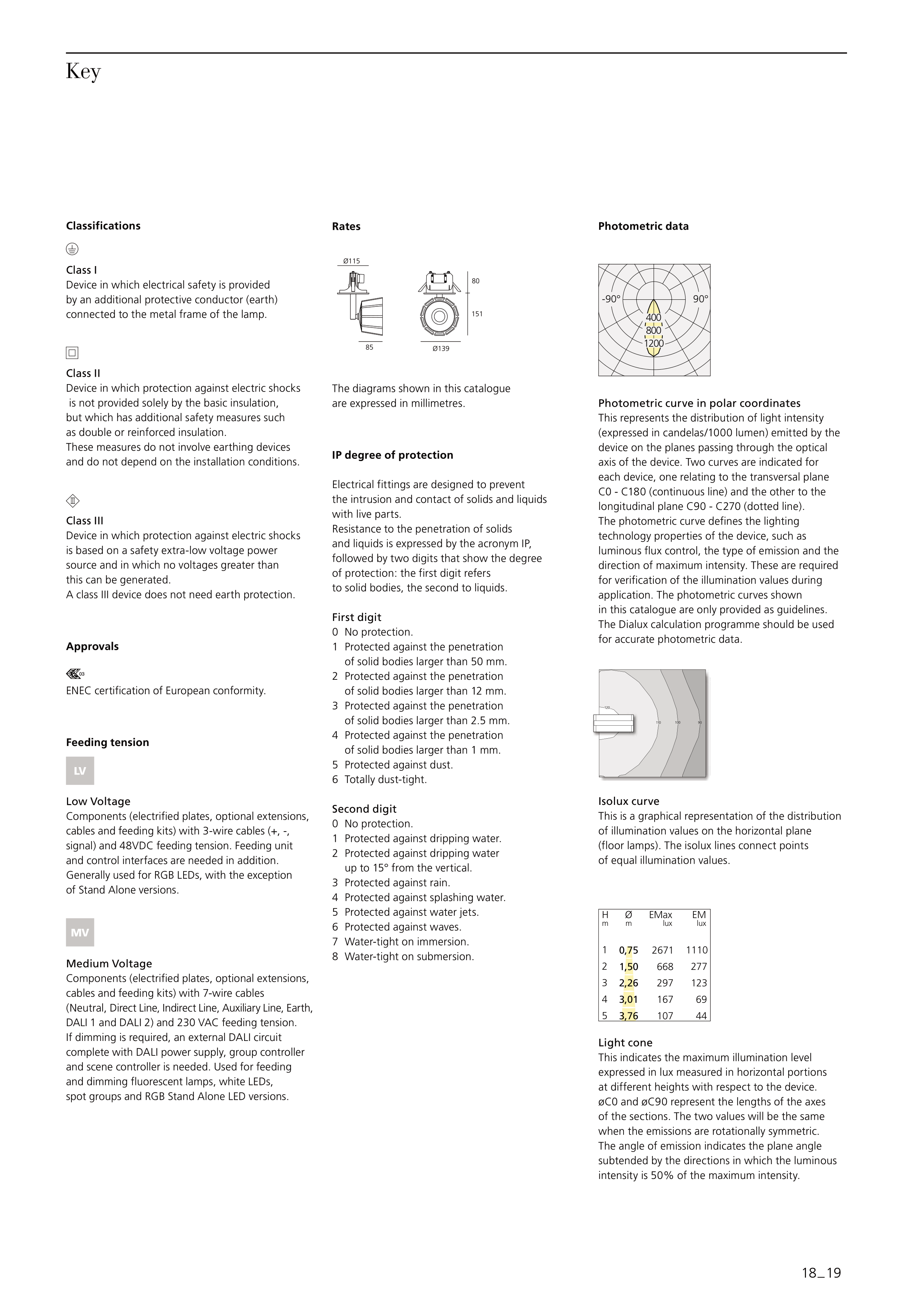
Rates
The diagrams shown in this catalogue
are expressed in millimetres.
IP degree of protection
Electrical fittings are designed to prevent
the intrusion and contact of solids and liquids
with live parts.
Resistance to the penetration of solids
and liquids is expressed by the acronym IP,
followed by two digits that show the degree
of protection: the first digit refers
to solid bodies, the second to liquids.
First digit
0 No protection.
1 Protected against the penetration
of solid bodies larger than 50 mm.
2 Protected against the penetration
of solid bodies larger than 12 mm.
3 Protected against the penetration
of solid bodies larger than 2.5 mm.
4 Protected against the penetration
of solid bodies larger than 1 mm.
5 Protected against dust.
6 Totally dust-tight.
Second digit
0 No protection.
1 Protected against dripping water.
2 Protected against dripping water
up to 15° from the vertical.
3 Protected against rain.
4 Protected against splashing water.
5 Protected against water jets.
6 Protected against waves.
7 Water-tight on immersion.
8 Water-tight on submersion.
Photometric data
Photometric curve in polar coordinates
This represents the distribution of light intensity
(expressed in candelas/1000 lumen) emitted by the
device on the planes passing through the optical
axis of the device. Two curves are indicated for
each device, one relating to the transversal plane
C0 - C180 (continuous line) and the other to the
longitudinal plane C90 - C270 (dotted line).
The photometric curve defines the lighting
technology properties of the device, such as
luminous flux control, the type of emission and the
direction of maximum intensity. These are required
for verification of the illumination values during
application. The photometric curves shown
in this catalogue are only provided as guidelines.
The Dialux calculation programme should be used
for accurate photometric data.
Isolux curve
This is a graphical representation of the distribution
of illumination values on the horizontal plane
(floor lamps). The isolux lines connect points
of equal illumination values.
Light cone
This indicates the maximum illumination level
expressed in lux measured in horizontal portions
at different heights with respect to the device.
øC0 and øC90 represent the lengths of the axes
of the sections. The two values will be the same
when the emissions are rotationally symmetric.
The angle of emission indicates the plane angle
subtended by the directions in which the luminous
intensity is 50% of the maximum intensity.
18 _ 19


